Title here
Summary here

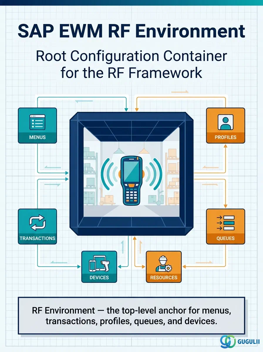
The RF Environment is the root-level master data object that anchors the entire SAP EWM Radio Frequency (RF) Framework. Identified by a three-character ID within a Warehouse Number, it groups every RF object — Menus, Logical Transactions, Profiles, Queues, and Presentation Devices — under a single configuration container. Nothing in the RF Framework can be created without an RF Environment defined first. This article covers the object’s role and hierarchy in Part 1 and the field-level configuration details in Part 2.
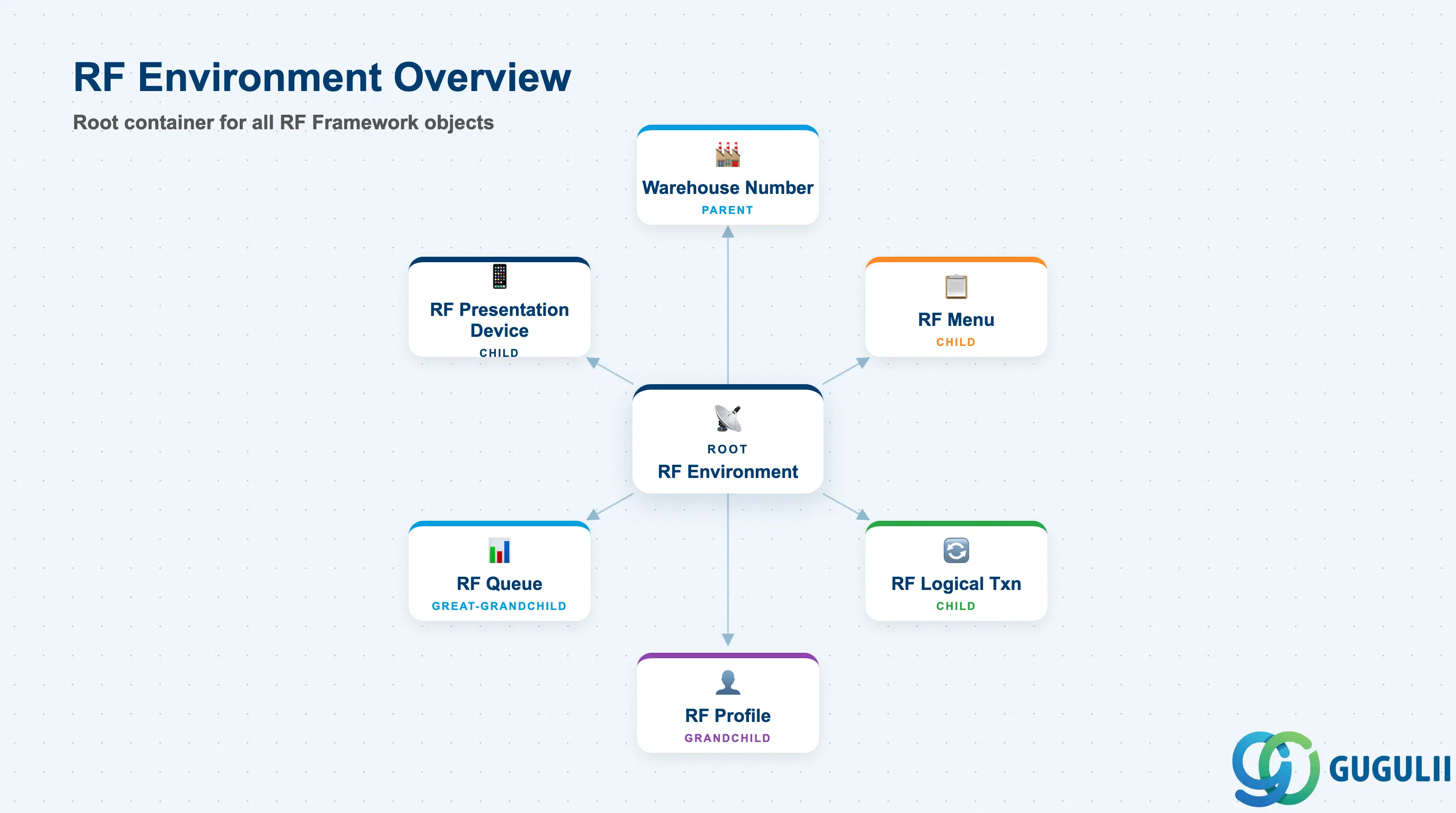
The RF Environment defines the top-level context in which all RF terminal activity in a warehouse takes place. Every RF object — menus, transactions, profiles, queues, and devices — is created within the scope of an RF Environment. A single warehouse can host multiple RF Environments to serve different process areas (for example, inbound receiving on one set of devices and outbound picking on another), but each object can belong to only one environment.
| Aspect | Details |
|---|---|
| Role | Root configuration container for the EWM RF Framework — defines the outer boundary within which all RF objects are created |
| Modules using it | EWM (primary and sole owner); used across Embedded Basic (B), Embedded Advanced (A), and Decentralized (D) deployments |
| Transactions | SPRO → EWM → Radio Frequency (RF) Framework → Define RF Environments; /SCWM/RF_ENV |
| Key Tables | /SCWM/TRFENV (RF environment header definition) |
| S/4HANA note | RF Framework is available in all EWM deployment options (B, A, D) from S/4HANA 1809 onwards. Configuration remains SPRO-based; no dedicated Fiori app for RF Environment definition as of S/4HANA 2023. |
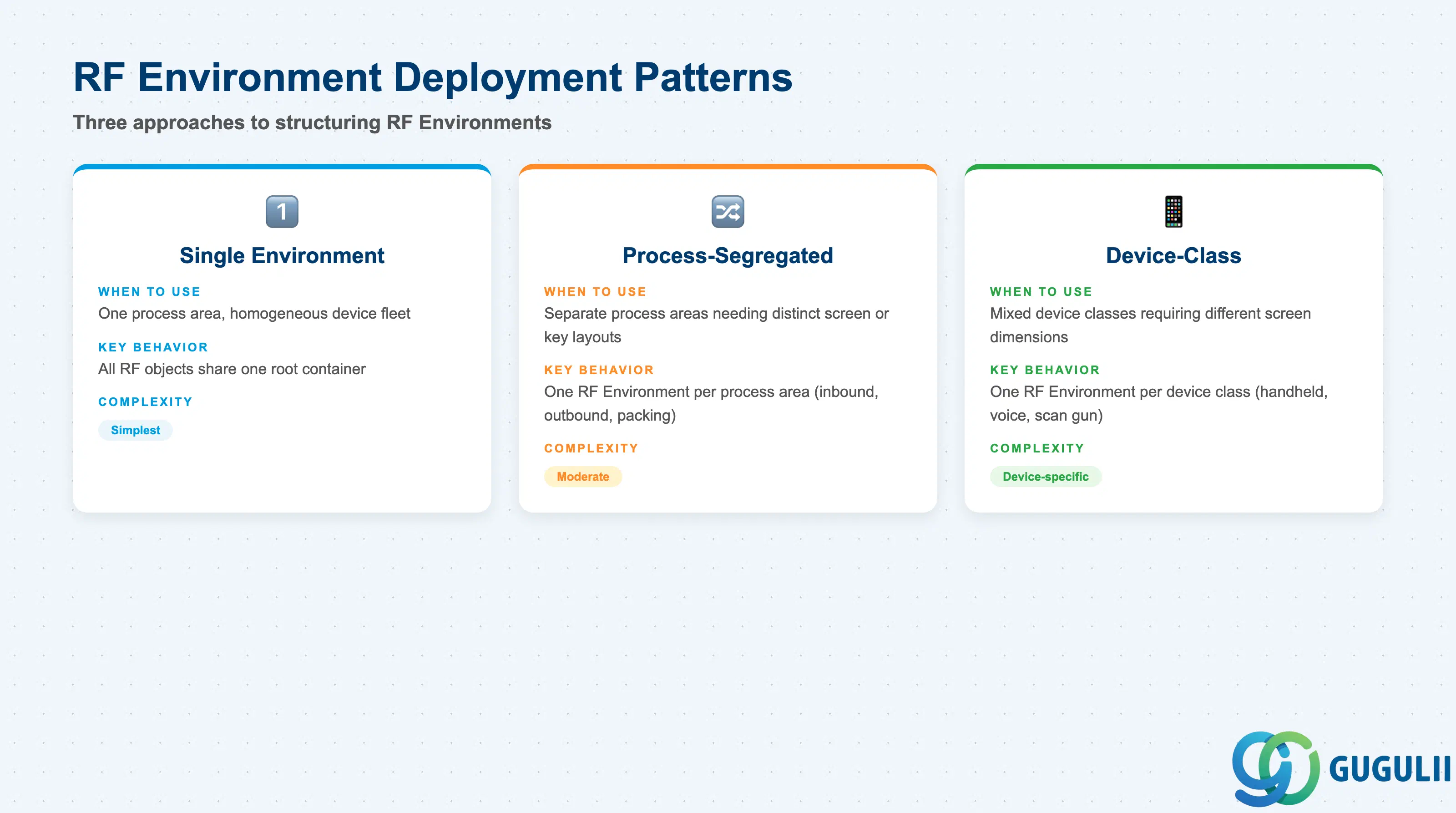
While SAP does not define formal “types” for RF Environments at the system level, there are three well-established deployment patterns that determine how many environments a warehouse needs. Choosing the wrong model early in a project forces painful reconfiguration of all child RF objects later.
| Pattern | When to Use | Key Behavior |
|---|---|---|
| Single Environment (Standard) | Warehouses with one process area and a homogeneous device fleet | All RF Menus, Profiles, and Presentation Devices share one root. Simplest to configure and maintain. |
| Process-Segregated Environments | Warehouses with clearly separated process areas (inbound, outbound, packing) each with distinct screen layouts or function key requirements | One RF Environment per process area. Enables independent screen format and function key profiles per area without interference. |
| Device-Class Environments | Warehouses running mixed device classes (classic RF handheld terminals + voice-directed devices + scan guns) requiring different screen dimensions | One RF Environment per device class. Screen size and column settings can be optimized per environment. |
Design principle: Fewer environments reduce maintenance overhead. Split into multiple environments only when screen format, function key layout, or language requirements genuinely differ between worker populations or device classes.
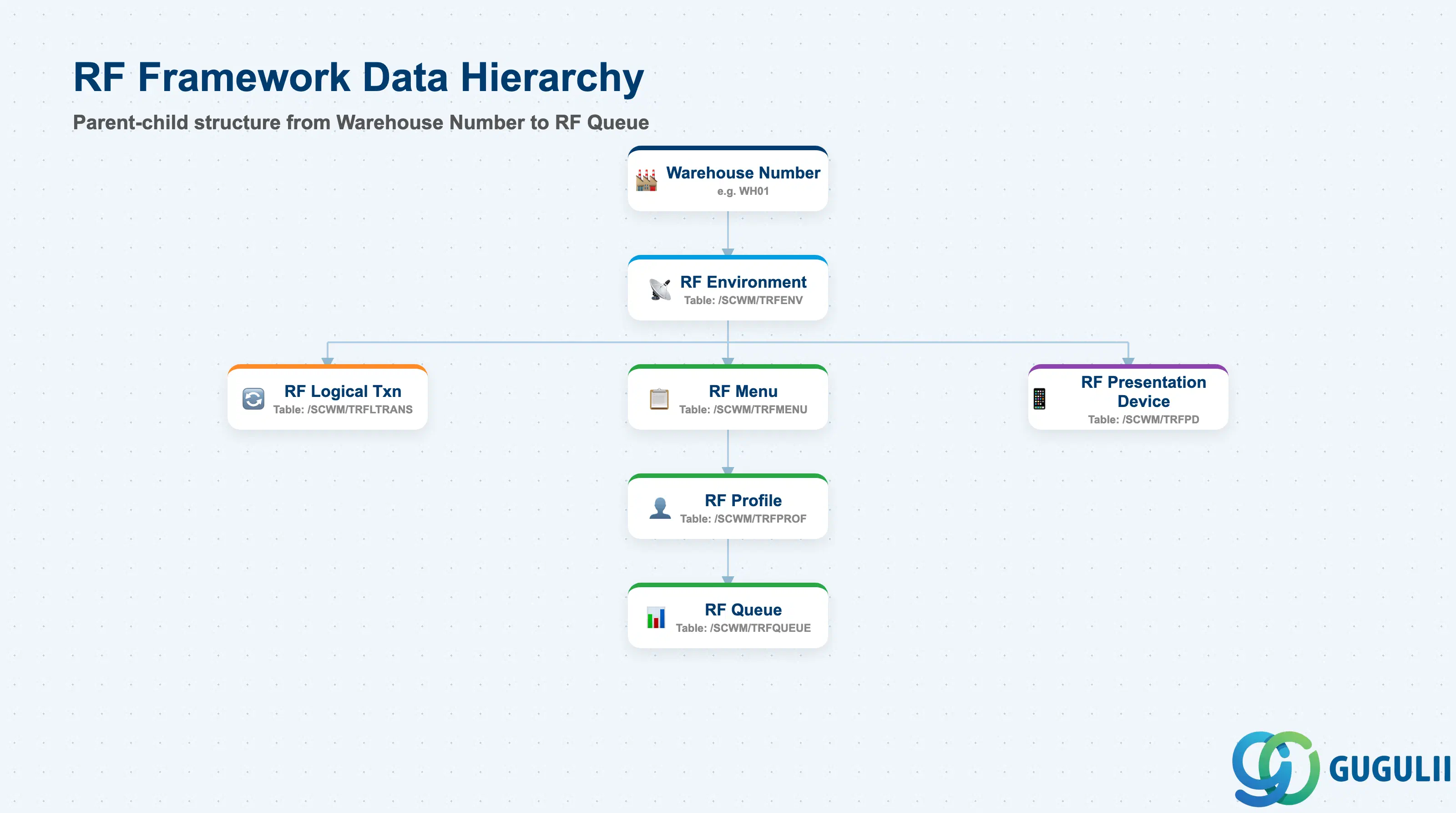
The RF Framework is organized as a strict parent-child hierarchy rooted in the Warehouse Number. The RF Environment is the first configurable level below the Warehouse Number and acts as the parent for every other RF object. No child object can exist across multiple environments — the environment boundary is hard.
Warehouse Number (e.g., WH01)
   │
   └── RF Environment (3-char ID, e.g., RF1)         ← /SCWM/TRFENV
          │
          ├── RF Logical Transaction                   ← /SCWM/TRFLTRANS
          │     (Defines executable business functions on the RF terminal)
          │
          ├── RF Menu                                  ← /SCWM/TRFMENU
          │     └── RF Profile                         ← /SCWM/TRFPROF
          │            └── RF Queue                    ← /SCWM/TRFQUEUE
          │
          └── RF Presentation Device                   ← /SCWM/TRFPD
(Registers physical RF terminal devices)| Org Level | Table | Primary Fields | Notes |
|---|---|---|---|
| Warehouse Number | EWM Warehouse configuration (SPRO) | Warehouse ID, description | Defined in SPRO before any RF object |
| RF Environment | /SCWM/TRFENV | Environment ID (3 chars), description, warehouse number, screen format, function key profile | Root of the RF Framework — all child objects reference this key |
| RF Logical Transaction | /SCWM/TRFLTRANS | LT ID, description, RF environment, step sequence | References the RF Environment key |
| RF Menu | /SCWM/TRFMENU | Menu ID, description, RF environment | References the RF Environment key |
| RF Profile | /SCWM/TRFPROF | Profile ID, menu ID, user/resource assignments | References the RF Menu |
| RF Queue | /SCWM/TRFQUEUE | Queue ID, profile ID, priority settings | References the RF Profile |
| RF Presentation Device | /SCWM/TRFPD | Device ID, RF environment, device type, screen format | References the RF Environment key directly |
Key design decision: The RF Environment ID (3 characters) is immutable after child objects are created. Agree on the naming convention (e.g., RCV, SHP, PKG) before any child objects are configured.
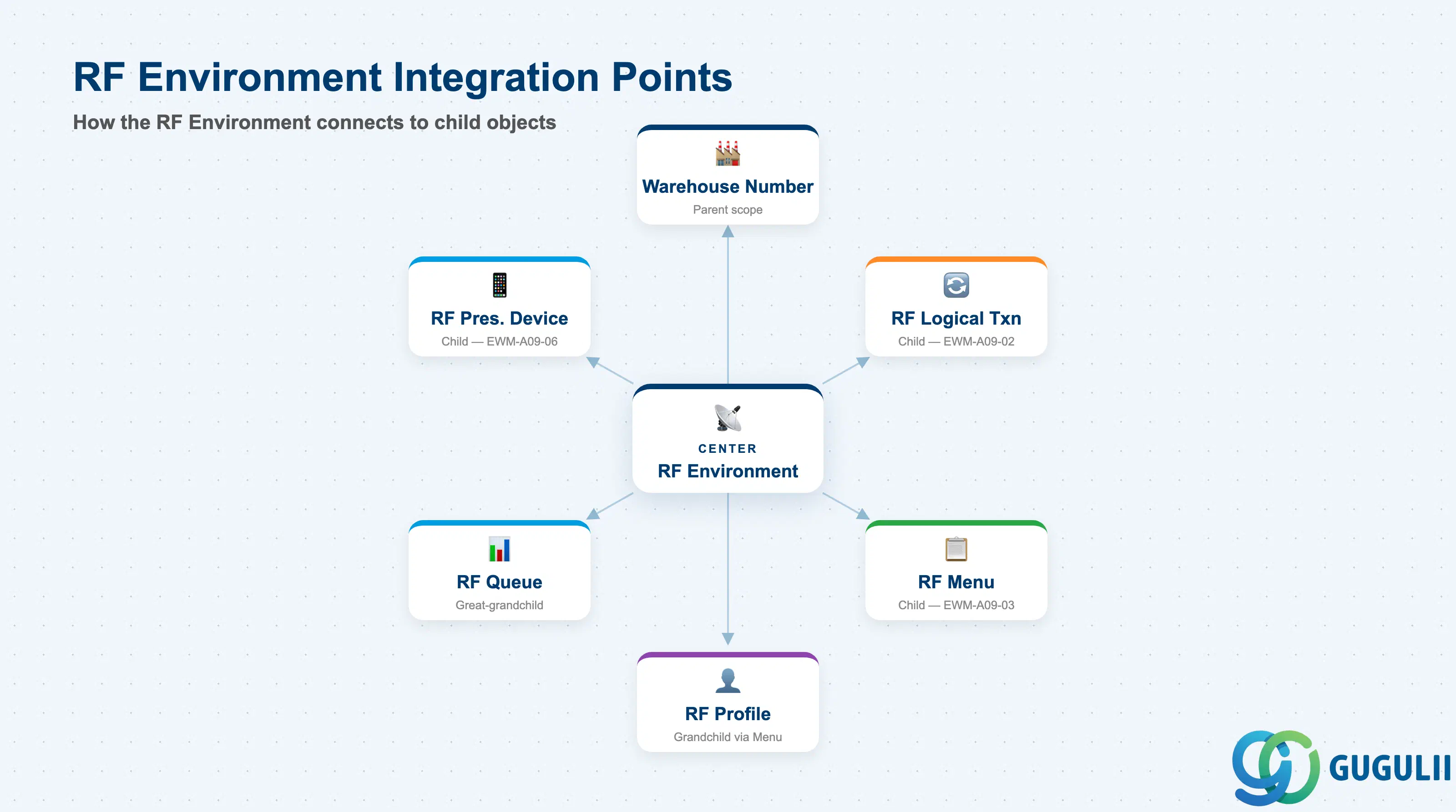
The RF Environment does not operate in isolation. It inherits its physical scope from the Warehouse Number and provides the parent reference for every child RF object. Understanding these integration points is essential when planning the RF Framework setup sequence.
| Object | Relationship | Practical Notes |
|---|---|---|
| Warehouse Number | Parent — RF Environment is defined within a Warehouse Number | The Warehouse Number must exist in SPRO before the RF Environment can be created. One Warehouse Number supports multiple RF Environments. |
| RF Logical Transaction (EWM-A09-02) | Child — RF Logical Transactions reference the RF Environment | Logical Transactions define the executable RF business functions (e.g., putaway, picking confirmation). They must be created within the RF Environment. |
| RF Menu (EWM-A09-03) | Child — RF Menus reference the RF Environment | The RF Menu structures which Logical Transactions are accessible to workers. Must reference a valid RF Environment. |
| RF Profile (EWM-A09-04) | Grandchild via RF Menu | Profiles assign users or resources to menus and control display settings. They are one level below the RF Menu, not direct children of the environment. |
| RF Queue (EWM-A09-05) | Great-grandchild via RF Profile | Queues control how warehouse tasks are pushed to RF terminals. They depend on an RF Profile, which depends on an RF Menu, which depends on the RF Environment. |
| RF Presentation Device (EWM-A09-06) | Child — RF Presentation Devices reference the RF Environment | Physical RF terminal devices are registered directly under the RF Environment. The screen format assigned to the device must be compatible with the environment’s screen settings. |
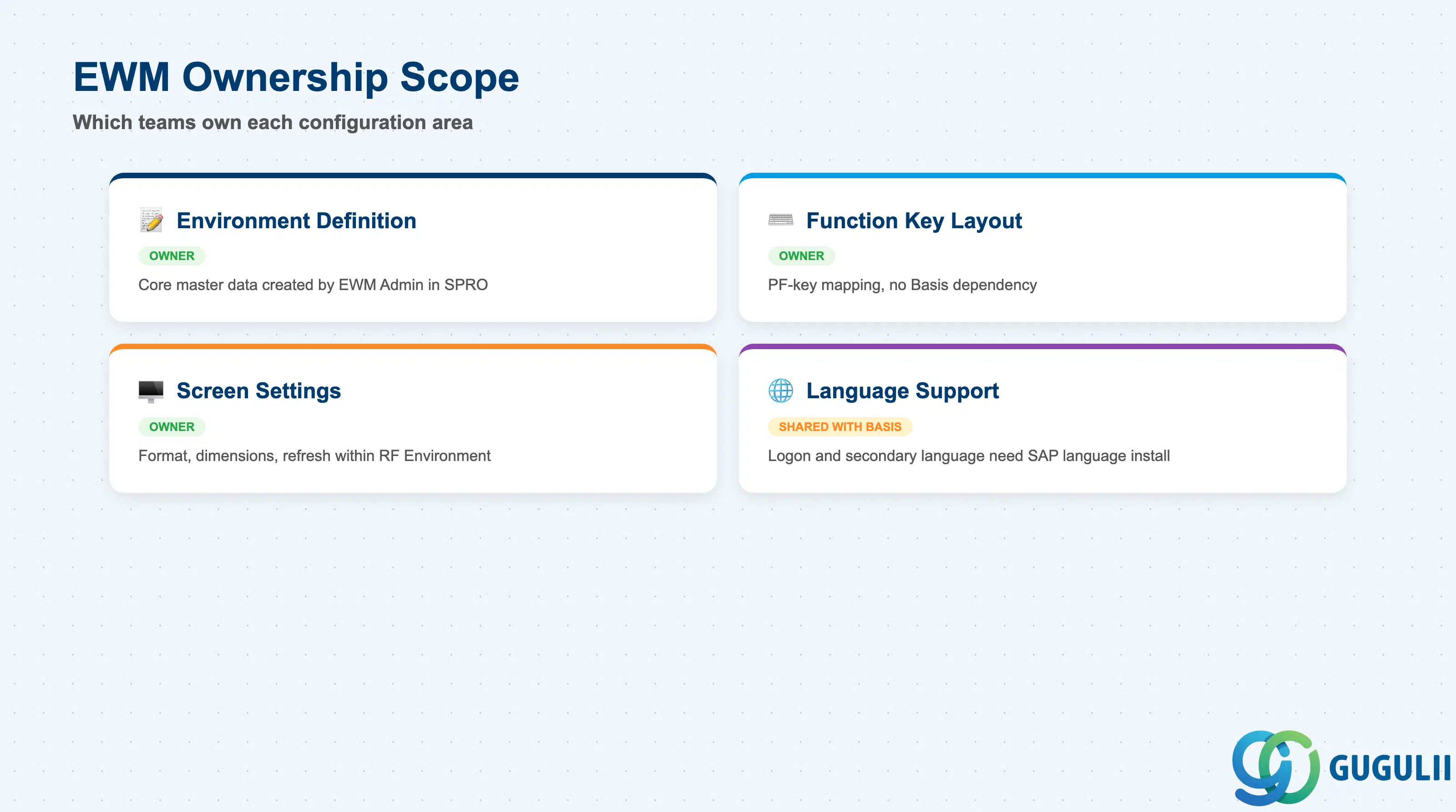
| Data Section | EWM Involvement | Notes |
|---|---|---|
| Environment Definition | ◎ Owner | Core master data record — created and maintained by EWM Administrator in SPRO |
| Function Key Layout | ◎ Owner | Function key profile and PF-key mapping are EWM-specific configuration; no Basis dependency |
| Screen Settings | ◎ Owner | Screen format, line/column dimensions, double-row mode, and refresh interval are defined within the RF Environment |
| Language Support | ○ Shared with Basis | Logon language and secondary language are configured in collaboration with Basis (SAP system language installation) |
Legend: ◎ = Owner / Critical, ○ = Direct involvement
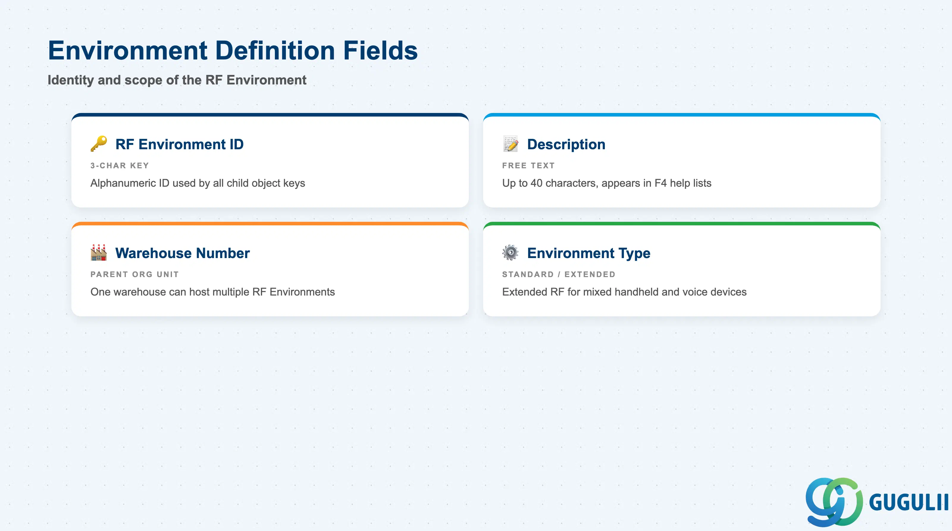
The Environment Definition section establishes the identity and scope of the RF Environment. These fields form the primary key used by all child RF objects and cannot be changed after child records exist.
| Field | Description | Practical Usage |
|---|---|---|
| RF Environment ID | 3-character alphanumeric identifier for the environment | Choose a meaningful, process-oriented code (e.g., RCV for receiving, SHP for shipping). This ID appears in all child object keys, so abbreviations that reflect the warehouse process area reduce confusion during support. |
| Description | Free-text description of the environment (up to 40 characters) | Use a consistent naming convention across warehouses in a client landscape (e.g., “WH01 Inbound RF Environment”). Descriptions appear in F4 help lists, so clarity here speeds day-to-day administration. |
| Warehouse Number | Organizational unit to which this RF Environment belongs | A single Warehouse Number can have multiple RF Environments. Confirm the Warehouse Number with the warehouse design before creating the environment — changing it requires deleting and re-creating all child objects. |
| Environment Type | Controls whether the environment uses standard RF protocol or extended RF functionality | Standard RF is suitable for most warehouse processes. Extended RF (also called mixed RF) is required when combining classic handheld terminal screens with voice-directed operation or other non-standard device types in the same process area. |
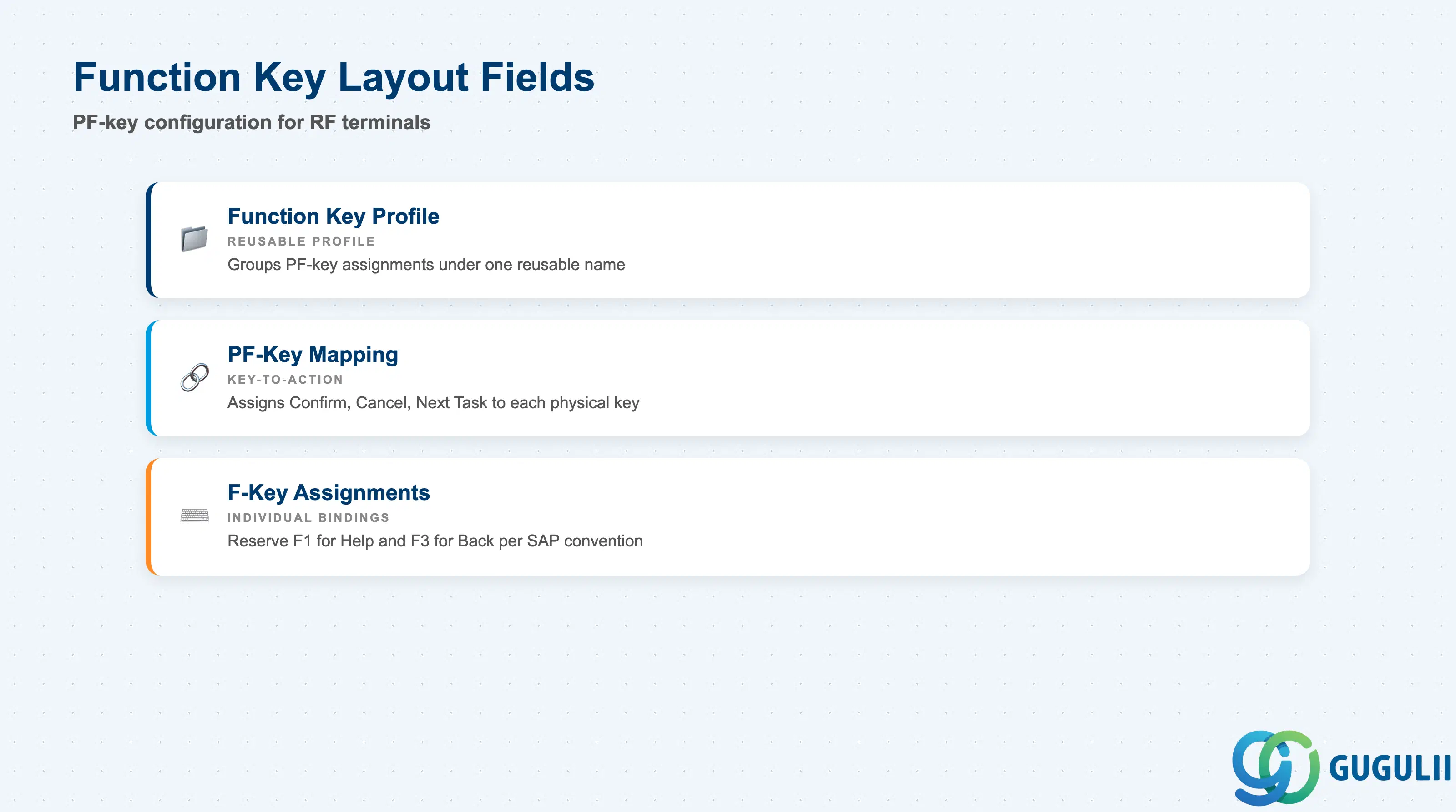
The Function Key Layout controls how the physical function keys (F-keys, PF-keys) on an RF handheld terminal are mapped to EWM system actions. Consistent function key layout across environments reduces worker errors and training time.
| Field | Description | Practical Usage |
|---|---|---|
| Function Key Profile | Groups a set of PF-key assignments under a reusable profile name | Create one profile per device class or process area and reuse it across environments where applicable. Modifying a shared profile affects all environments that reference it, so isolate profiles when process areas have unique key requirements. |
| PF-Key Mapping | Assigns a specific EWM action (e.g., Confirm, Cancel, Next Task) to each physical function key | Map the most frequently performed action to the key closest to the worker’s thumb on the dominant hand. For automotive or manufacturing warehouses with high-cycle picking, ergonomic key assignment measurably reduces task confirmation time. |
| F-Key Assignments | Individual key-to-action bindings within the PF-Key Mapping | Reserve F1 for Help and F3 for Back to comply with SAP UI conventions — workers moving between SAP GUI and RF sessions will expect these defaults. Deviating from convention increases support calls. |
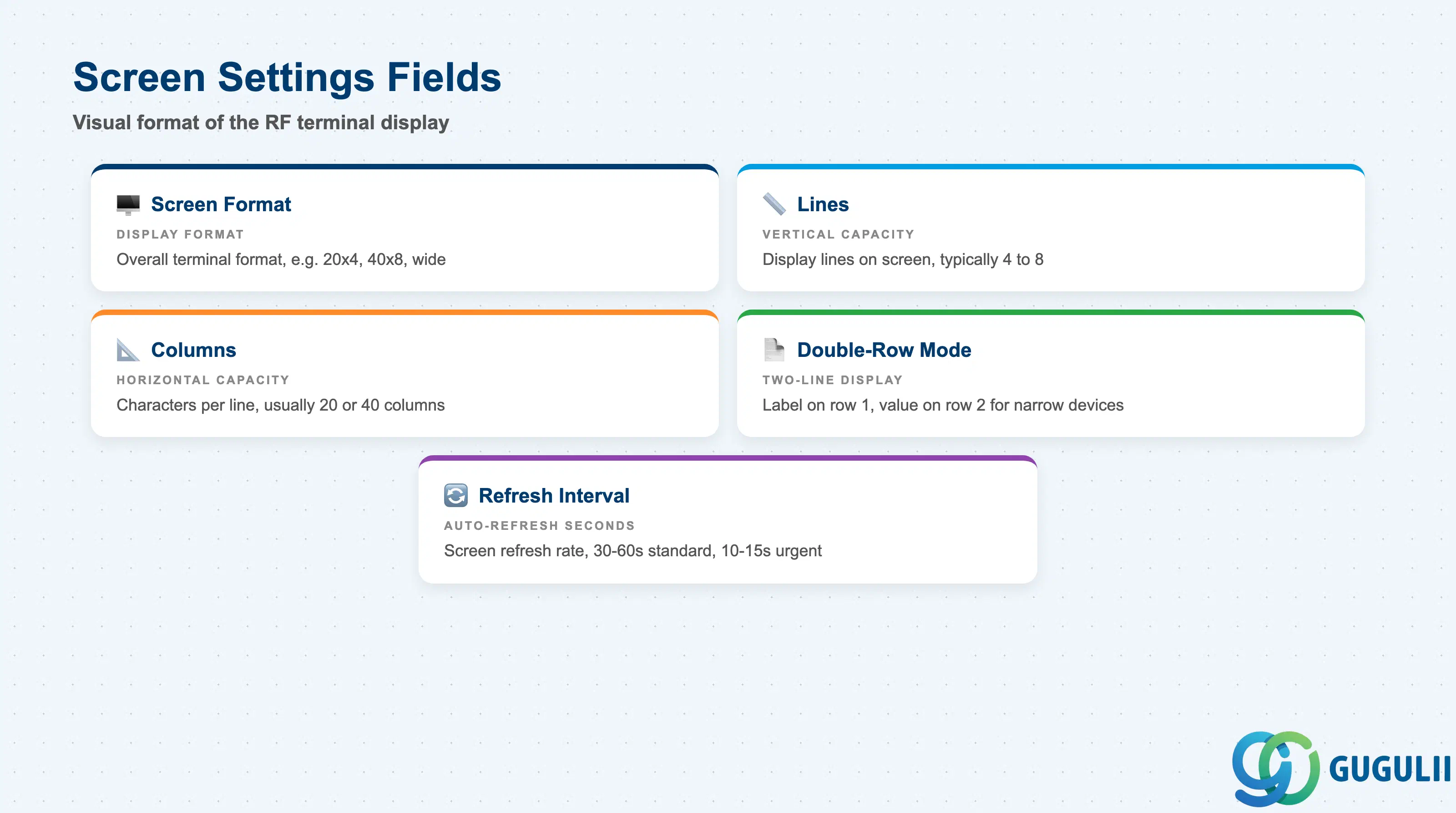
Screen Settings define the visual format of the RF terminal display. These settings must match the physical capabilities of the RF devices that will be registered as RF Presentation Devices under this environment. A mismatch between environment screen settings and physical device capabilities causes display truncation or blank screens.
| Field | Description | Practical Usage |
|---|---|---|
| Screen Format | Defines the overall terminal screen format (e.g., 20x4, 40x8, wide-screen) | Select the format that matches the smallest-screen device in the environment. Using a larger format on a small-screen device truncates field labels. In mixed-device warehouses, create separate environments for each screen class rather than compromising on a lowest-common-denominator format. |
| Lines | Number of display lines available on the terminal screen | Standard RF handhelds typically support 4–8 lines. Verify the physical device specification before configuring. Increasing line count beyond the device’s physical capability has no effect and wastes configuration effort. |
| Columns | Number of character columns per display line | Most EWM RF transactions are designed for 20-column displays. Wider column counts (40+) enable more descriptive field labels but require wider-screen devices. |
| Double-Row Mode | Enables two-line display per data field (label on row 1, value on row 2) | Activate for environments with narrow-column devices (20-char) where standard single-row display truncates long field names. Doubles the screen space consumed per field, so verify that the most complex RF transactions still fit within the available line count. |
| Refresh Interval | Time in seconds between automatic screen refreshes for queue-driven task display | Set to 30–60 seconds for standard pick-and-confirm workflows. Reduce to 10–15 seconds in environments where tasks are pushed urgently (e.g., replenishment triggers from an automated conveyor). Overly short intervals increase server load in high-volume warehouses. |
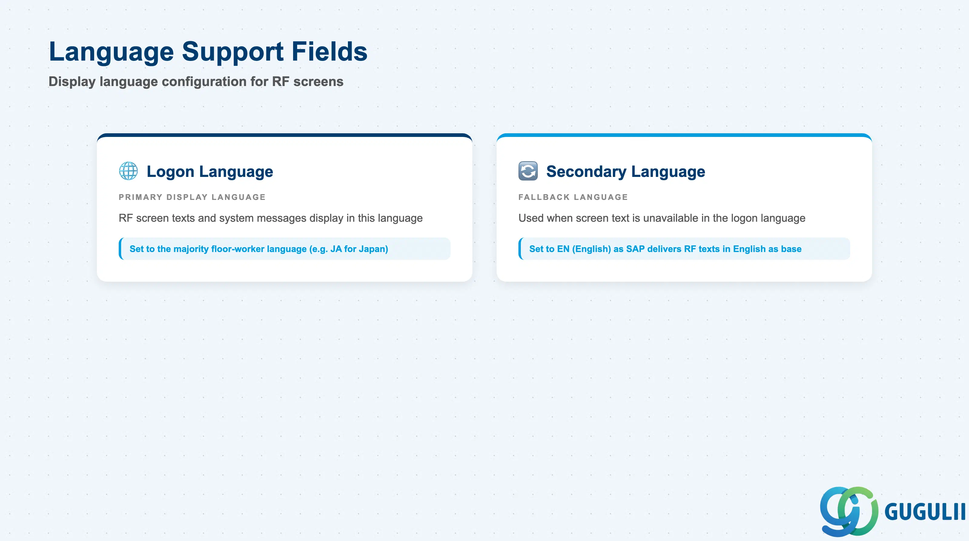
Language Support determines in which language the RF terminal screens are displayed. Configuration requires coordination with Basis to confirm that the required SAP system languages are installed.
| Field | Description | Practical Usage |
|---|---|---|
| Logon Language | Primary language used for RF screen texts and system messages | Set to the language spoken by the majority of floor workers. In Japan-based warehouses, setting this to JA displays all RF screen labels and error messages in Japanese, reducing worker errors caused by unfamiliar English field names. |
| Secondary Language | Fallback language when a screen text is not available in the logon language | Set to EN (English) as the secondary language in most deployments. SAP delivers RF screen texts in English as the base language; any custom or partner-added screens that lack a translation will fall back to this language rather than displaying blank labels. |
| ID | Category | Title |
|---|---|---|
| ewm-001 | Overview | What is SAP EWM? |
| ID | Category | Title |
|---|---|---|
| ewm-b01 | Overview | SAP EWM Transactions: Process Flow, Hierarchy & Relationships |