Title here
Summary here
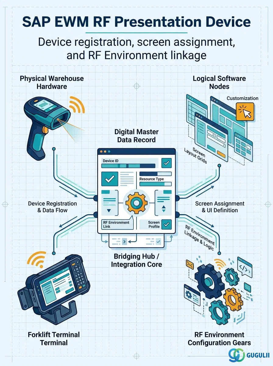
The RF Presentation Device is the master data record that represents one RF terminal — scanner, vehicle-mount terminal, or workstation — within a specific SAP EWM warehouse. It stores the logical identity of each device and binds it to an RF Environment, which in turn determines the screen size, display layout, and available transactions the device can render. Without a Presentation Device record, a physical terminal cannot log into the RF Framework and receive warehouse task assignments. This article maps the object’s role in the RF Framework, its device categories, its organizational scope, its integration with adjacent RF master data, and the key configuration fields EWM consultants own during setup.
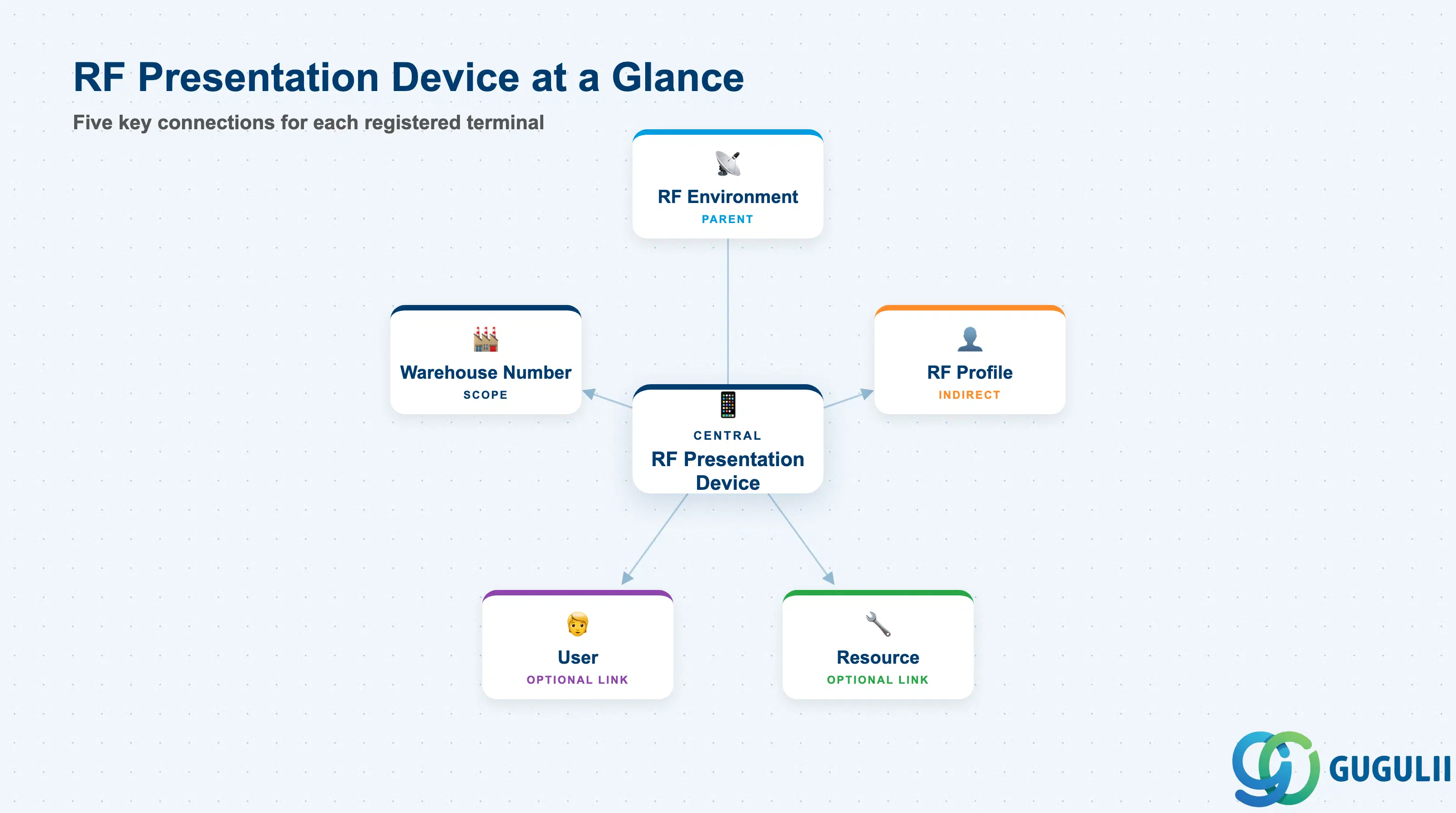
The RF Presentation Device record gives SAP EWM a software representation of a specific piece of hardware — or a named logical device — that warehouse operators use to execute tasks via the RF Framework. Each record identifies the device by a unique name within the warehouse, specifies the RF Environment it belongs to (which governs screen dimensions and available function keys), and optionally links to a user or resource. When a warehouse worker picks up a scanner and logs in, EWM resolves the session to the matching Presentation Device record and applies the correct display profile.
| Aspect | Details |
|---|---|
| Role | Registers individual RF terminals (scanners, VMTs, workstations) in EWM and links each to an RF Environment for display control |
| Modules using it | EWM (RF Framework — primary owner): all three deployment modes (Embedded Basic, Embedded Advanced, Decentralized) |
| Transactions | /SCWM/RFPD (Create / Change / Display RF Presentation Device) |
| Key Tables | /SCWM/RFPDEV (RF Presentation Device header), /SCWM/RFPD_USR (optional user assignment) |
| S/4HANA note | Available in all EWM deployment variants (Embedded Basic, Embedded Advanced, Decentralized EWM). No structural change from ECC-based Decentralized EWM. Configuration remains in /SCWM/RFPD. |
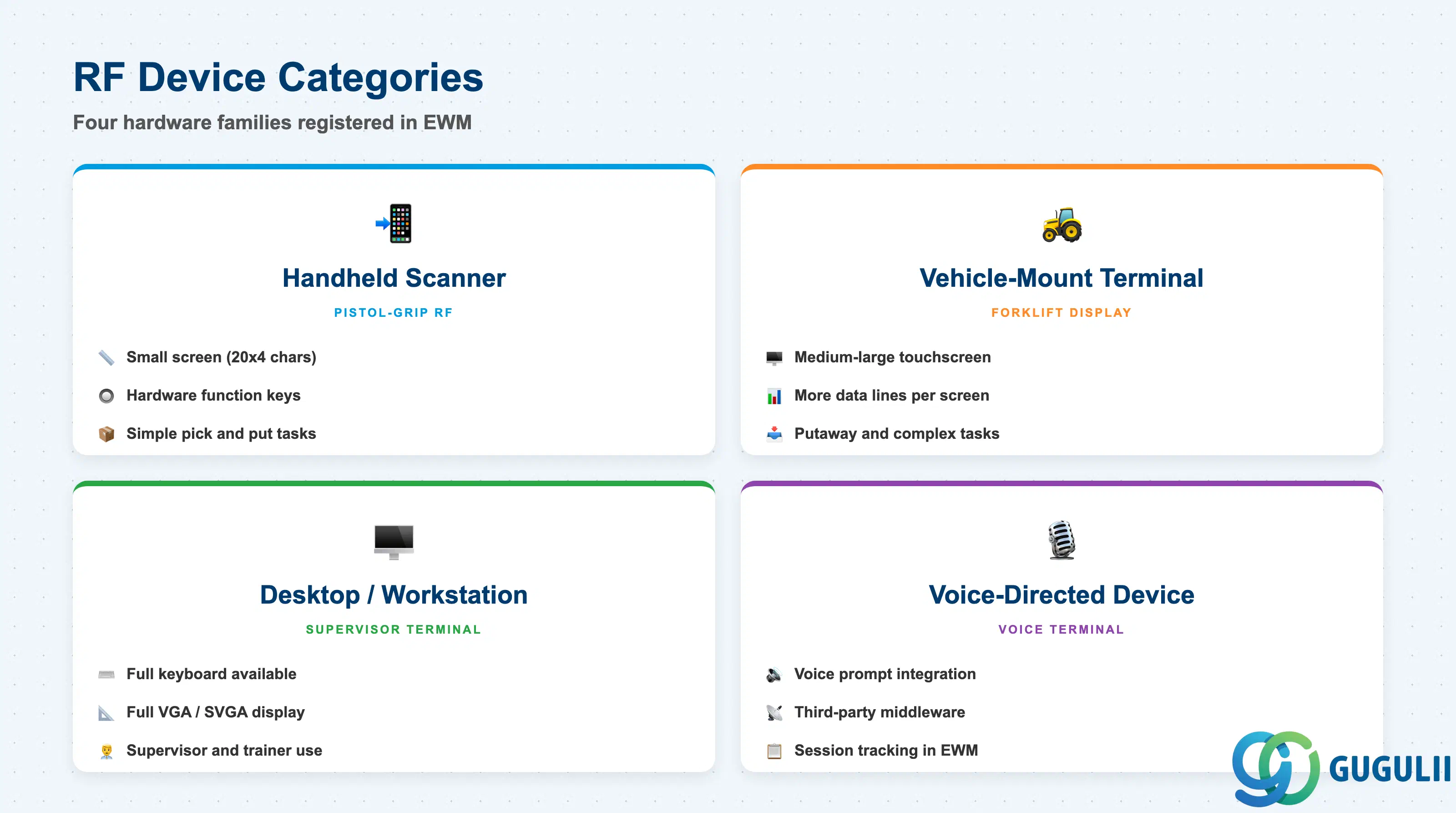
EWM does not enforce a rigid taxonomy of device hardware at the system level — the Presentation Device record is a logical registration that the administrator names and categorizes freely. However, the most important configuration choice is which RF Environment the device belongs to, because the RF Environment encodes screen dimensions and function key layout. Misassigning a small-screen handheld to a large-screen environment (or vice versa) causes display truncation or wasted space that operators find unusable in practice.
| Device Category | Typical Hardware | Screen Size Profile | Key Behavior |
|---|---|---|---|
| Handheld Scanner | Zebra, Honeywell pistol-grip barcode scanner | Small (e.g., 20×4 characters or 240×320 px) | Minimal display; function keys mapped to hardware buttons; suited for simple pick/put tasks |
| Vehicle-Mount Terminal (VMT) | Forklift-mounted touchscreen terminal | Medium to large (e.g., 800×600 or 1024×768 px) | Larger display area; can show more data lines per screen; suited for putaway and complex transactions |
| Desktop / Workstation | Standard PC or thin client running the RF GUI emulator | Large (full VGA / SVGA) | Supervisor or trainer use; full keyboard available; all screen real estate used |
| Voice-Directed Device | Vocollect, Honeywell voice terminal | Screen size often minimal or display-less | Voice prompt integration via third-party middleware; device still registered in EWM for session tracking |
Design principle: Define one RF Environment per distinct screen size family used in the warehouse, then register every device of that family under the corresponding environment. Mixing device types under one environment leads to display inconsistencies that are difficult to fix after go-live.
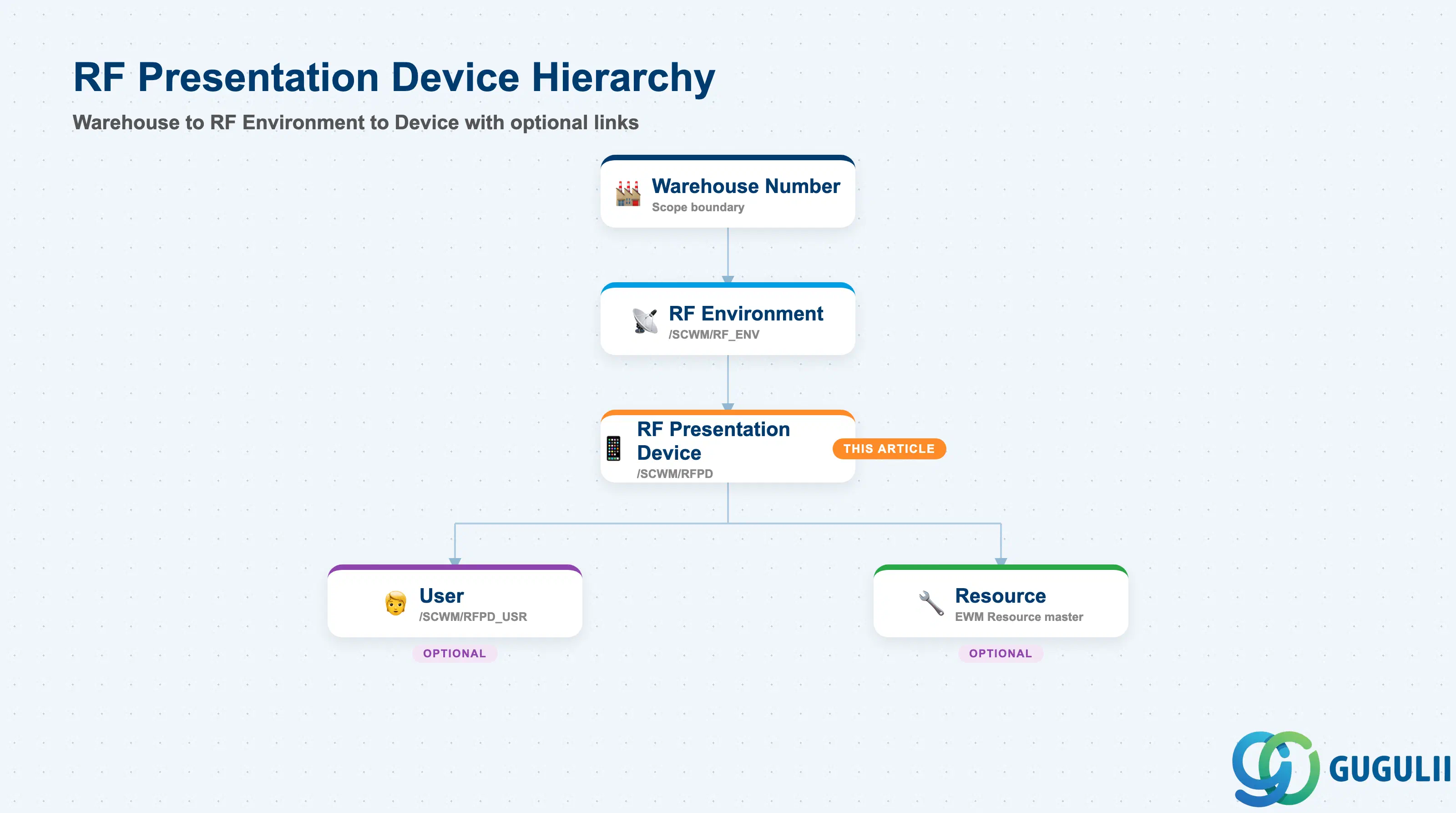
The RF Presentation Device sits at the lowest level of the RF Framework master data hierarchy. All its parent objects must exist before the device record can be created. The device itself is scoped to a single Warehouse Number via the RF Environment it references — cross-warehouse device sharing is not supported.
Warehouse Number (EWM)
   │
   └── RF Environment  (/SCWM/RF_ENV)
          │  (defines screen size, function key layout, active languages)
          │
          └── RF Presentation Device  (/SCWM/RFPD)
                 │  (registers one physical/logical terminal)
                 │
                 ├── [Optional] User assignment  (/SCWM/RFPD_USR)
                 │      (ties a specific SAP user to this device)
                 │
                 └── [Optional] Resource reference
(links to an EWM Resource for forklift / operator tracking)| Org Level | Object | Primary Fields | Notes |
|---|---|---|---|
| Warehouse | Warehouse Number | Warehouse ID | All RF Framework objects are scoped per warehouse |
| RF Environment | RF Environment | Screen rows/columns, function key set, active language | One RF Environment per screen size family; referenced by the device |
| Device | RF Presentation Device | Device name, device type, RF Environment, user assignment | One record per physical terminal or named logical device |
Key design decision: Create the RF Environment before the Presentation Device. The screen dimensions defined in the RF Environment cannot be overridden at the device level — all devices sharing an environment share identical display geometry.
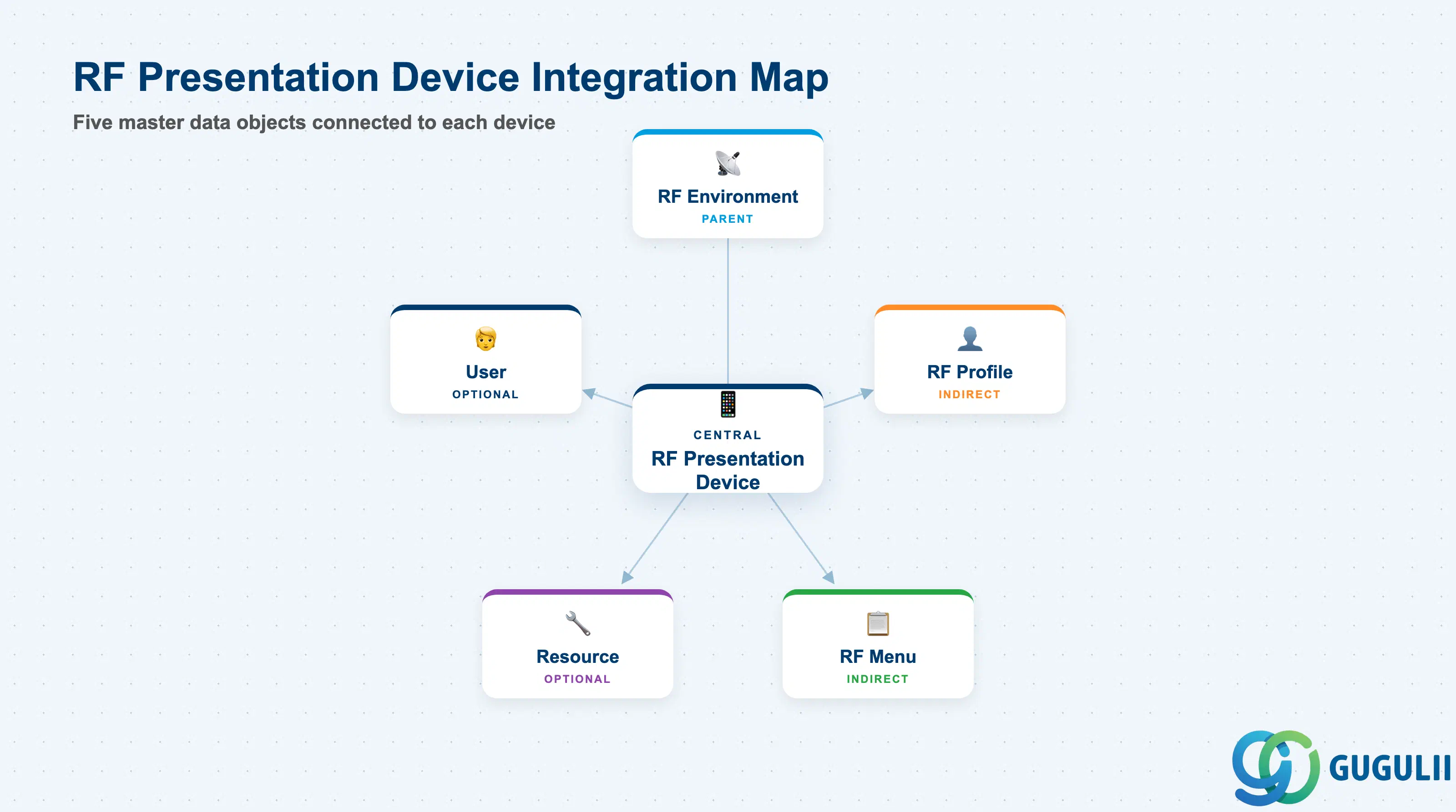
The RF Presentation Device is the endpoint object in the RF Framework chain, but it interacts with several sibling master data objects at runtime. The device record itself is configuration-only; runtime behaviour is controlled by the RF Profile assigned to the user or resource that logs into the device.
| Object | Relationship | Practical Notes |
|---|---|---|
| RF Environment | Parent — mandatory reference | Each Presentation Device belongs to exactly one RF Environment. The environment defines screen dimensions and function key configuration. |
| RF Profile | Indirect — via logged-in user or resource | The RF Profile (assigned to the user or resource, not the device) controls which RF Menu and RF Queues the operator sees after login. The device determines only how the output is rendered. |
| RF Menu | Indirect — via RF Profile | The menu tree presented to the operator on login is resolved through the RF Profile, not the device. The same device can show different menus to different users. |
| RF Queue | Indirect — via RF Profile | Work items routed to the operator arrive via the RF Queue defined in the RF Profile. The Presentation Device itself has no queue assignment. |
| Resource | Optional direct link | A Presentation Device can be associated with an EWM Resource (forklift, picker), enabling forklift tracking and resource-based task routing. |
| User | Optional direct link | A specific SAP user ID can be pre-assigned to a device, simplifying login on fixed-operator terminals. On shared scanners this field is left blank. |
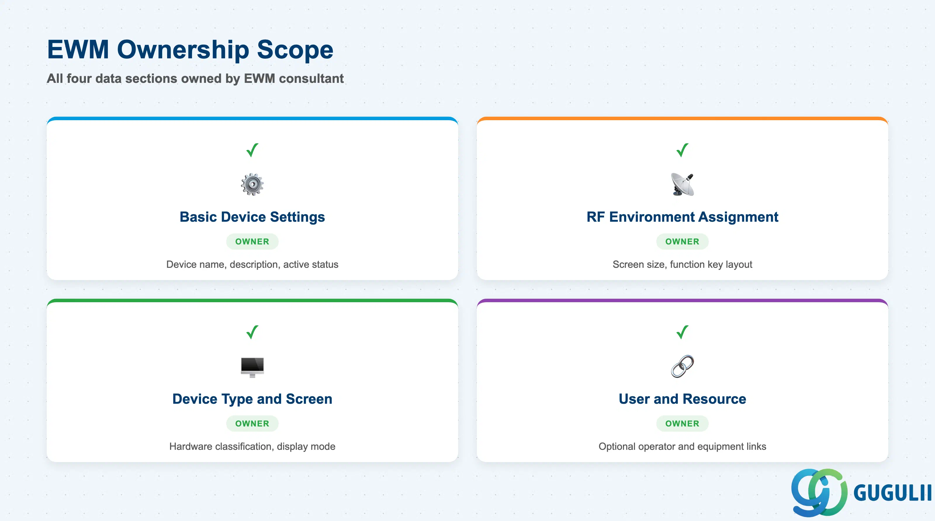
| Data Section | EWM Involvement | Notes |
|---|---|---|
| Basic Device Settings | ◎ Owner | Device name, description, and active/inactive status are maintained exclusively by the EWM Administrator in /SCWM/RFPD |
| RF Environment Assignment | ◎ Owner | The RF Environment link is the most critical field and is set once; changing it after go-live impacts all sessions on that device |
| Device Type and Screen Configuration | ◎ Owner | Device type code and screen size override (if any) are set by the EWM Administrator; must match the physical hardware |
| User and Resource Assignment | ◎ Owner | Optional fields; assigned by EWM Administrator in coordination with Basis (user IDs) and floor management (resource allocation) |
Legend: ◎ = Owner / Critical
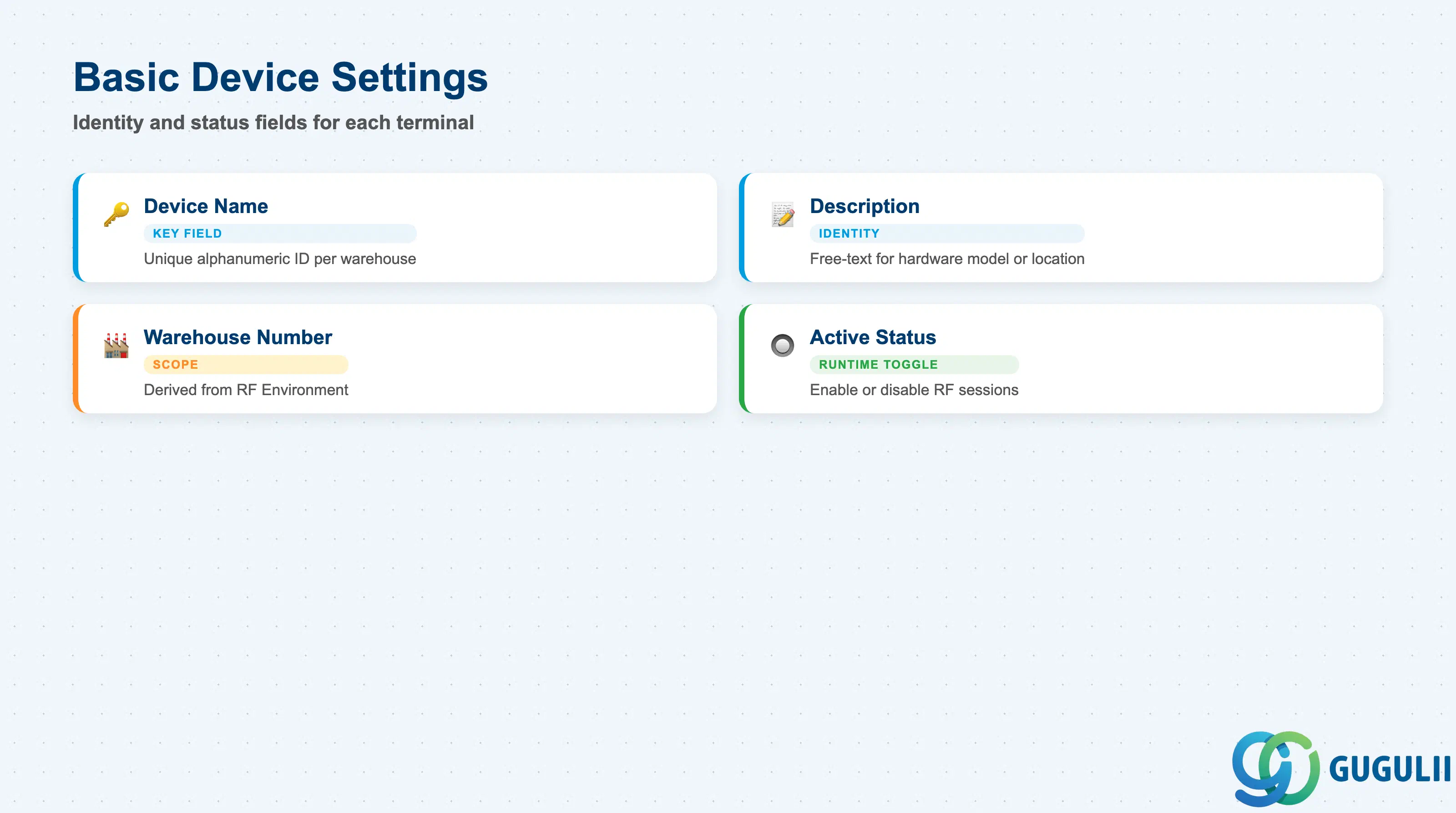
The Basic Device Settings section of the RF Presentation Device record defines the identity and status of the terminal within the EWM system. These fields are established at creation and rarely change — the device name in particular is often stamped on the physical hardware as a barcode or label for asset tracking purposes.
| Field | Description | Practical Usage |
|---|---|---|
| Device Name | Unique alphanumeric identifier for the Presentation Device within the warehouse | Keep naming conventions short and meaningful (e.g., HH-001 for handheld, VMT-010 for forklift terminal). Many sites align the Device Name with the physical asset tag on the scanner. Changing the name after go-live requires updating any user training materials and floor labels that reference it. |
| Description | Free-text description of the device | Use to document the physical location or hardware model (e.g., “Zebra TC72 — Receiving Dock A”). This field is consulted during troubleshooting when a device ID alone is ambiguous. |
| Warehouse Number | EWM Warehouse Number to which this device belongs | Derived automatically from the RF Environment assignment, but displayed here for reference. A device cannot span multiple warehouses — create separate records per warehouse if the same physical terminal is used across warehouse numbers (uncommon but possible in multi-warehouse EWM setups). |
| Active Status | Flag indicating whether the device is available for RF sessions | Set to active before go-live and deactivate when a terminal is retired, lost, or under maintenance. Inactive devices cannot initiate RF sessions, which helps control license compliance in large RF fleets. |
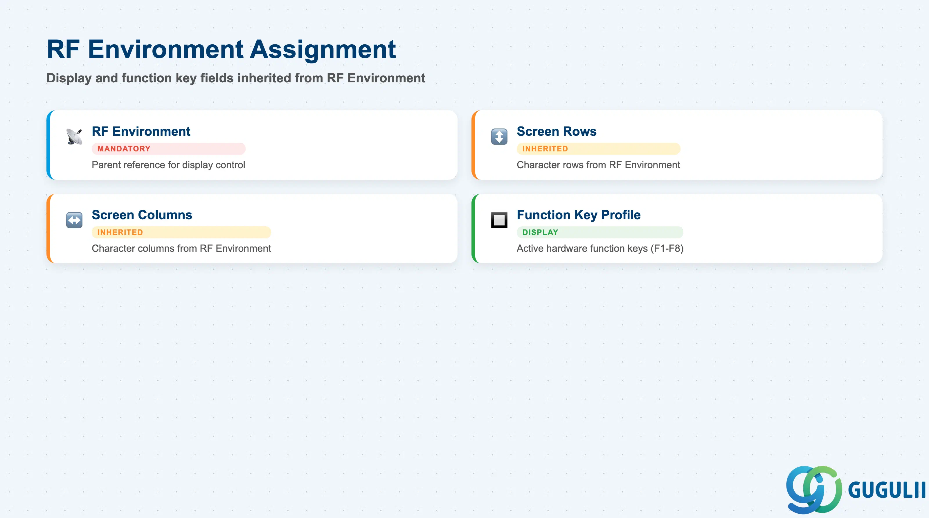
The RF Environment Assignment section is the most consequential part of the Presentation Device record because it determines every aspect of the display rendered on the terminal. The RF Environment itself is maintained in a separate master record (/SCWM/RF_ENV) and stores the screen row/column count and function key layout; the Presentation Device simply points to it.
| Field | Description | Practical Usage |
|---|---|---|
| RF Environment | Reference to the parent RF Environment master record | This is a mandatory field. Select the RF Environment whose screen dimensions match the physical terminal’s display. Assigning a mismatched environment (e.g., a 24-row environment to a 4-row scanner) results in display corruption or truncated output that is invisible in the sandbox but immediately apparent on the shop floor. Always verify the environment’s row/column settings against the hardware specification sheet before assignment. |
| Screen Rows (display) | Number of character rows the terminal can display — inherited from the RF Environment | Read-only on the device record; controlled by the RF Environment. If a new hardware model with different dimensions is introduced, a new RF Environment must be created rather than editing the existing one (which would affect all devices under it). |
| Screen Columns (display) | Number of character columns the terminal can display — inherited from the RF Environment | Same inheritance logic as Screen Rows. EWM’s standard screen templates (RF Logical Transactions) are designed for specific column widths; using a non-standard column count requires custom screen layouts. |
| Function Key Profile | Set of physical function keys available on this terminal — defined in RF Environment | Documents which hardware function keys (F1–F8, etc.) are active. Operators frequently need this information during training to understand which physical button triggers which EWM action. |
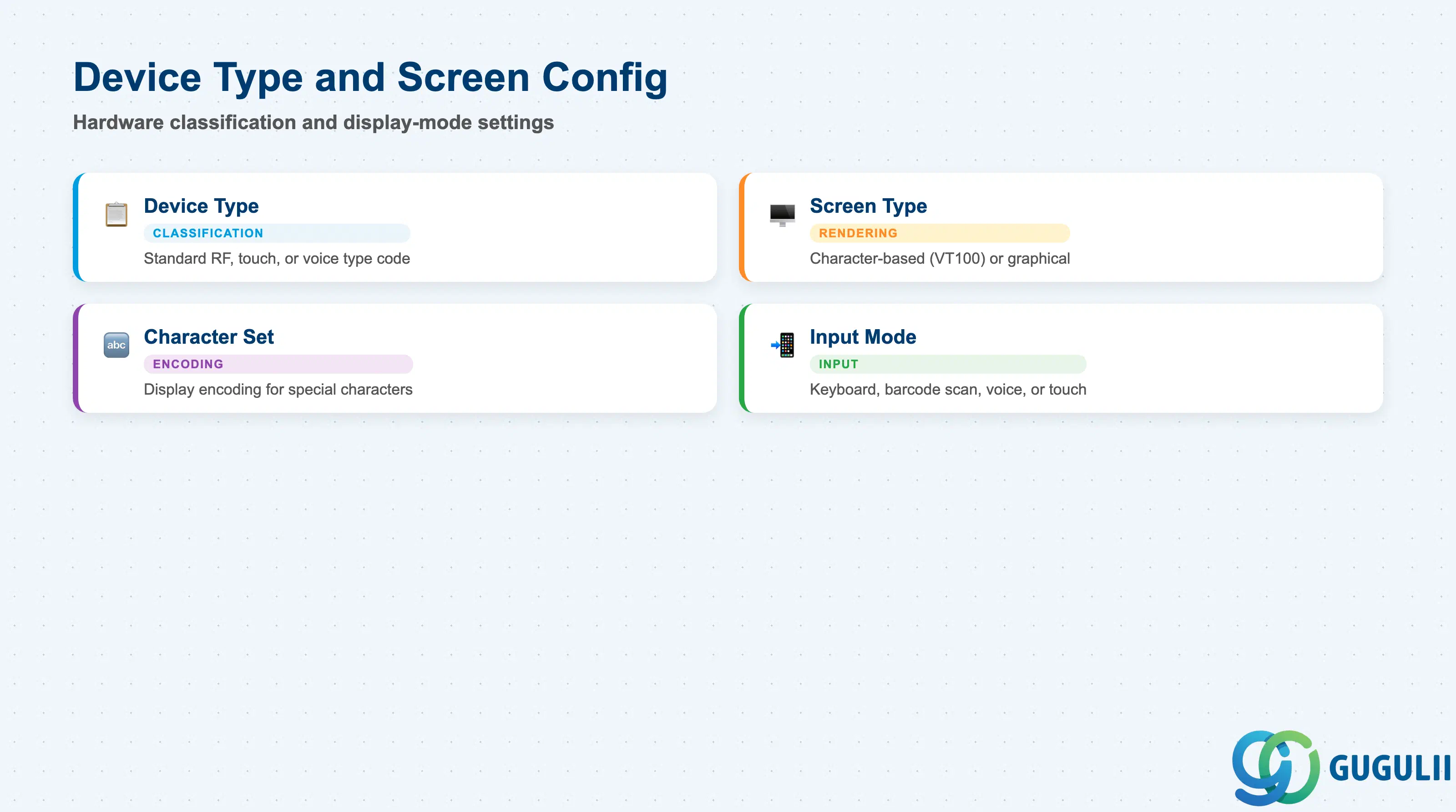
The Device Type and Screen Configuration section captures the hardware classification of the terminal and any display-mode settings that affect how EWM renders its RF screens. These fields allow EWM to adapt output formatting to the hardware’s capabilities, particularly for mixed-device warehouses where handheld scanners and vehicle-mount terminals coexist.
| Field | Description | Practical Usage |
|---|---|---|
| Device Type | Classification code indicating the hardware category of the terminal (e.g., standard RF, touch, voice) | Used internally by EWM to determine which screen rendering logic to apply. Most warehouses use the standard RF device type. Touch-capable terminals may require the TOUCH type to enable touch-input field navigation. Confirm the correct code with the RF hardware vendor before the EWM project blueprint is finalized. |
| Screen Type | Defines the display technology — character-based (telnet/VT100) vs. graphical (browser-based RF or ITS Mobile) | Character-based screen types use the classic telnet/5250 rendering optimized for scanner hardware. Graphical screen types (used with ITS Mobile or browser-based RF) allow richer layouts but add middleware complexity. Most industrial EWM deployments use character-based screens for reliability. |
| Character Set | Character encoding for the device display | Set to match the terminal’s firmware character set. Mismatches cause garbled display of special characters (particularly relevant for warehouses with Japanese, Chinese, or European language labeling on materials). |
| Input Mode | Defines how the terminal accepts operator input — keyboard scan, barcode scan, voice, or touch | Set according to the primary input method of the physical device. For barcode scanners, the scan input mode auto-populates EWM fields with scanned values; keyboard mode requires manual entry, which increases error rates in high-volume picking environments. |
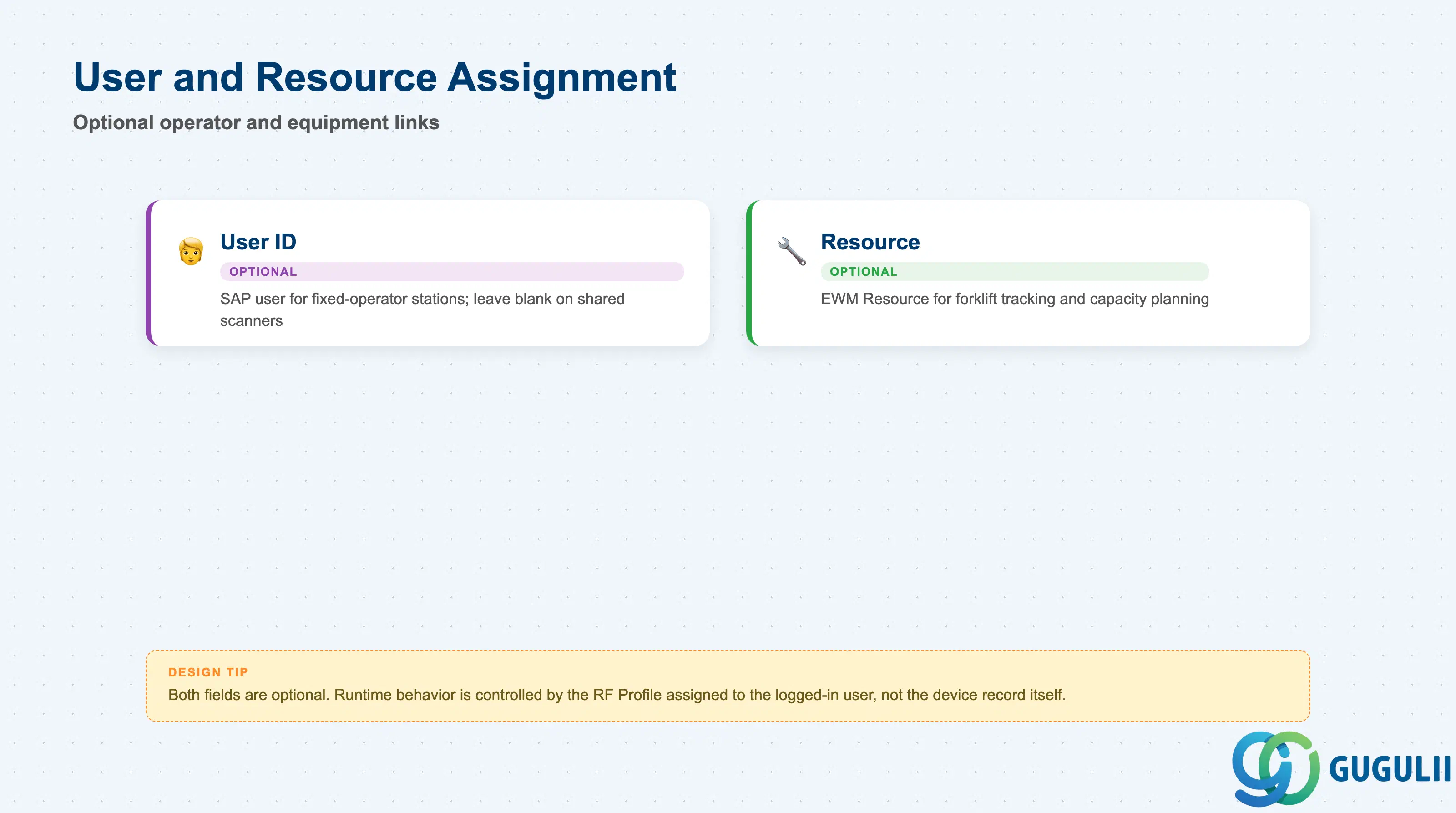
The User and Resource Assignment section links the Presentation Device to the specific operator or equipment unit that habitually uses it. Both fields are optional — many warehouses leave them blank and rely on the RF Profile (assigned per user) to control task routing. However, pre-assigning a resource to a device enables resource-based tracking capabilities such as forklift utilization reports and capacity-based queue filtering.
| Field | Description | Practical Usage |
|---|---|---|
| User ID | SAP user ID of the operator permanently assigned to this terminal | Use on fixed-operator stations (supervisor terminal, receiving desk) where one person is always associated with the device. Leave blank on shared pool scanners to avoid constraining who can log in. If populated, EWM can auto-populate the user on login, reducing keystrokes for permanent staff. |
| Resource | Reference to an EWM Resource master record (forklift, picker, AGV) | Assigning a Resource enables EWM to track the device’s location and workload as a warehouse resource. This is particularly valuable for forklift terminals — linking the VMT to the forklift Resource allows the Resource Planning function to schedule and monitor the vehicle. Leave blank for handheld scanners that are not associated with a specific vehicle. |
| ID | Category | Title |
|---|---|---|
| ewm-001 | Overview | What is SAP EWM? |
| ID | Category | Title |
|---|---|---|
| ewm-b01 | Overview | SAP EWM Transactions: Process Flow, Hierarchy & Relationships |