Title here
Summary here

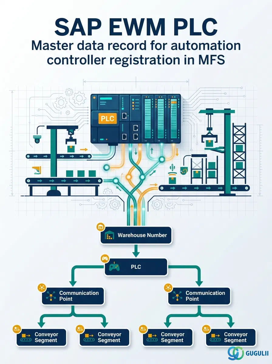
The PLC (Programmable Logic Controller) master data record is the topmost object in SAP EWM’s Material Flow System (MFS) hierarchy. It represents the physical automation controller — a hardware device that governs conveyor equipment, sorters, and automated storage/retrieval systems — and stores the network address, protocol, and assignment settings EWM needs to communicate with that device. Once a PLC record is created under a Warehouse Number, operators can attach one or more Communication Points to it, and Conveyor Segments are then linked to those Communication Points, forming the three-tier chain that drives automated material flow control.
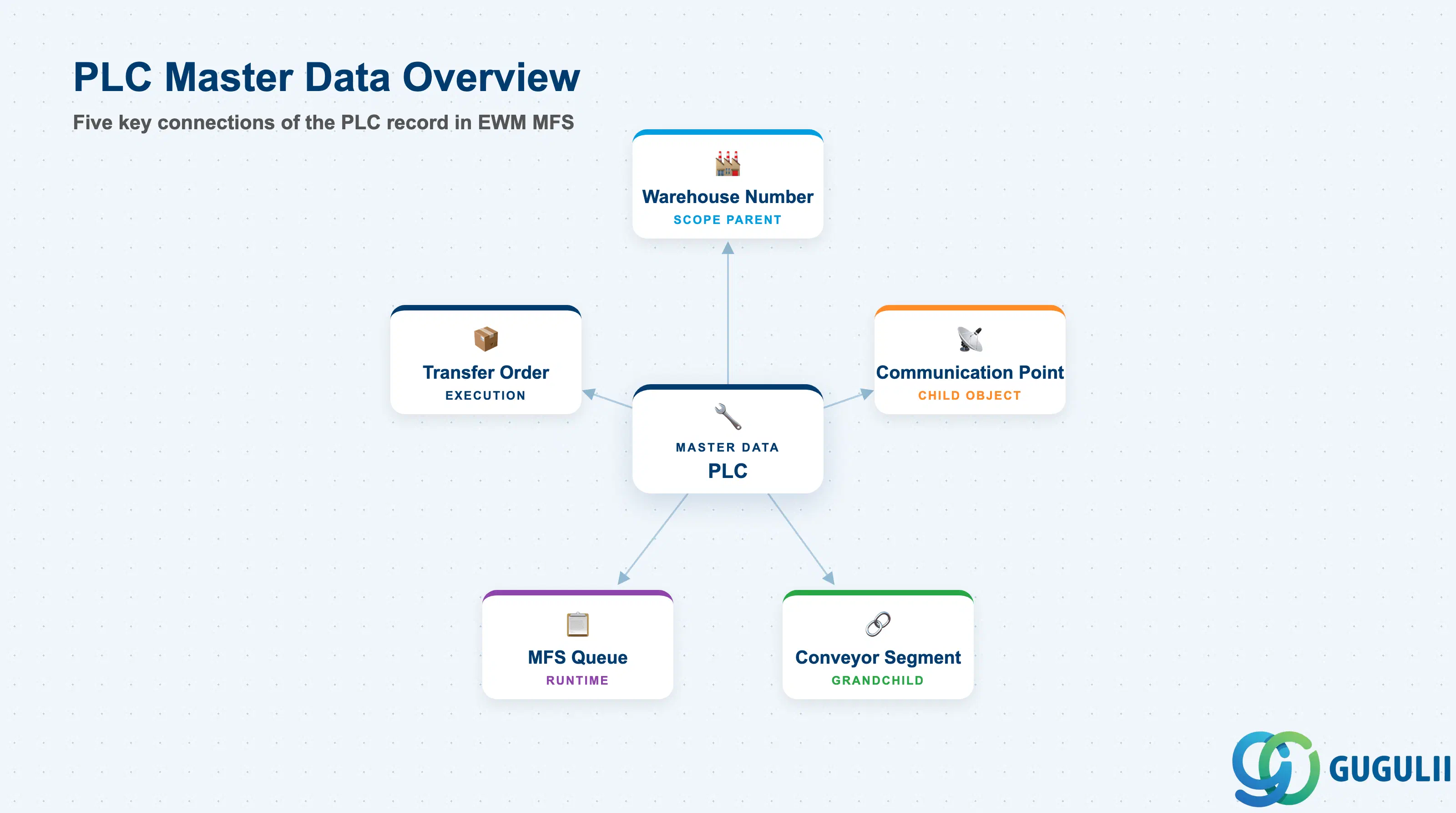
A Programmable Logic Controller is a ruggedized industrial computer designed to control machinery on a factory or warehouse floor. In SAP EWM, the PLC master data record does not program the controller itself — it provides EWM with the addressing and protocol information required to exchange telegram-based messages with the controller during warehouse operations.
| Aspect | Details |
|---|---|
| Role | Registers a physical automation controller device; provides the network endpoint (IP address, port, protocol) that EWM uses to send and receive MFS telegrams |
| Modules using it | EWM (MFS — primary owner); Decentralized EWM only; not available in Embedded Basic or Embedded Advanced editions |
| Transactions | /SCWM/MFS (MFS Configuration including PLC, Communication Point, Conveyor Segment) |
| Key Tables | /SCWM/MFS_PLC (PLC header), /SCWM/MFS_CP (Communication Point — child), /SCWM/MFS_CS (Conveyor Segment — grandchild) |
| S/4HANA note | MFS and the PLC master data record require Decentralized EWM. In Embedded EWM scenarios (Basic or Advanced), MFS is not supported; automated material flow is handled via custom RFC or third-party middleware instead. |
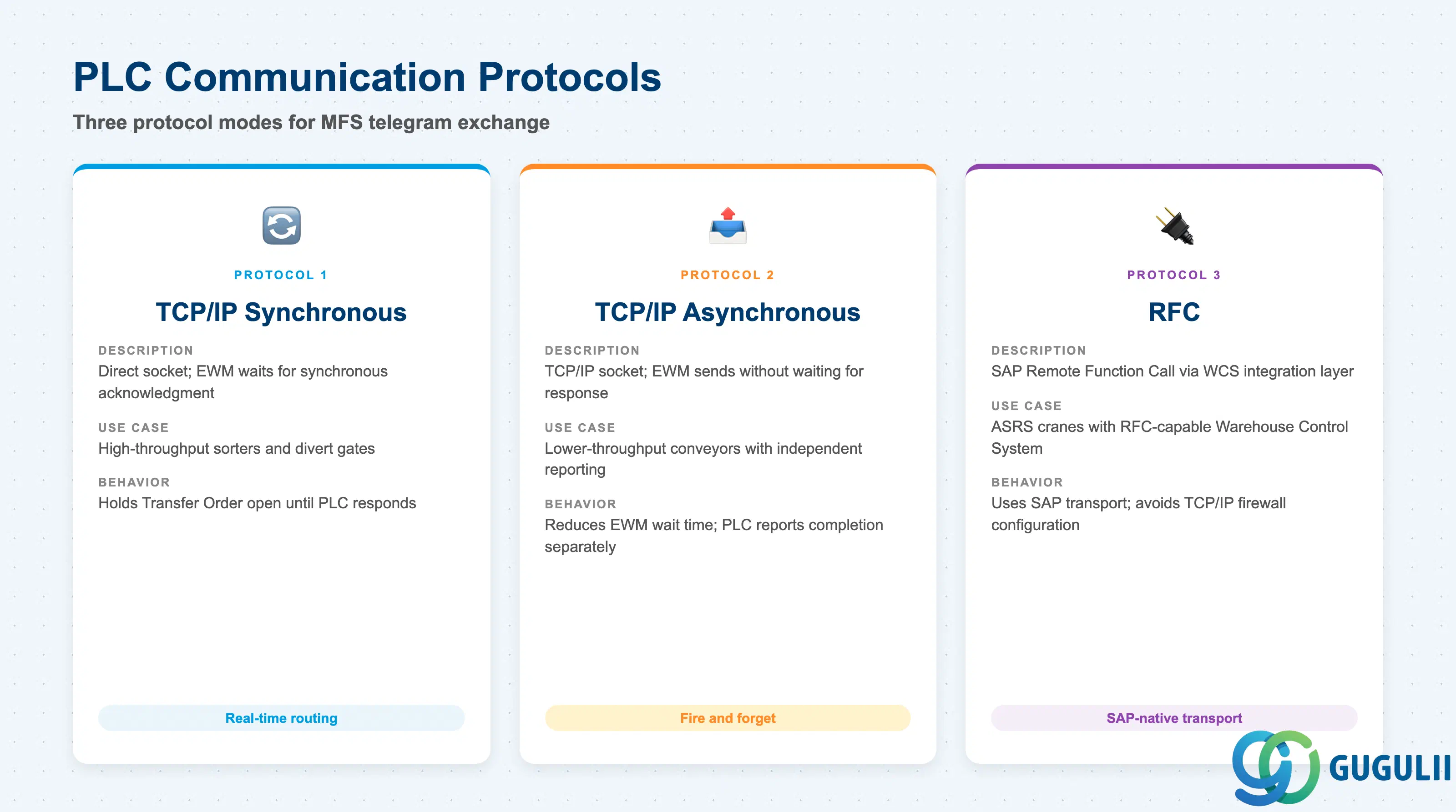
EWM does not classify PLCs into named business types the way it does for, say, Storage Types. Instead, the meaningful dimension is the communication protocol configured on the PLC master record, because the protocol determines which telegram format EWM uses when exchanging messages with the device.
| Protocol / Mode | Description | Use Case | Key Behavior |
|---|---|---|---|
| TCP/IP (Synchronous) | Direct socket connection over TCP/IP; EWM sends a telegram and waits for a synchronous acknowledgment | High-throughput conveyors where EWM controls material routing decision in real time | EWM holds the Transfer Order open until the PLC responds; suited for sorters and divert gates |
| TCP/IP (Asynchronous) | TCP/IP socket; EWM sends telegram without waiting for a response | Lower-throughput equipment or equipment that reports completion independently via a separate inbound telegram | Reduces EWM wait time; appropriate when the PLC’s own control loop handles sequencing |
| RFC | SAP-proprietary Remote Function Call; used when the automation system has an SAP integration layer rather than a bare-metal TCP/IP interface | Automated cranes (ASRS) managed by a Warehouse Control System (WCS) that exposes an RFC interface | Leverages existing SAP transport; avoids firewall port configuration for TCP/IP |
Design principle: Protocol selection must be confirmed with the PLC vendor and the MFS integration design team before system setup begins. Switching protocol after telegrams are configured requires regeneration of all telegram templates for that PLC.
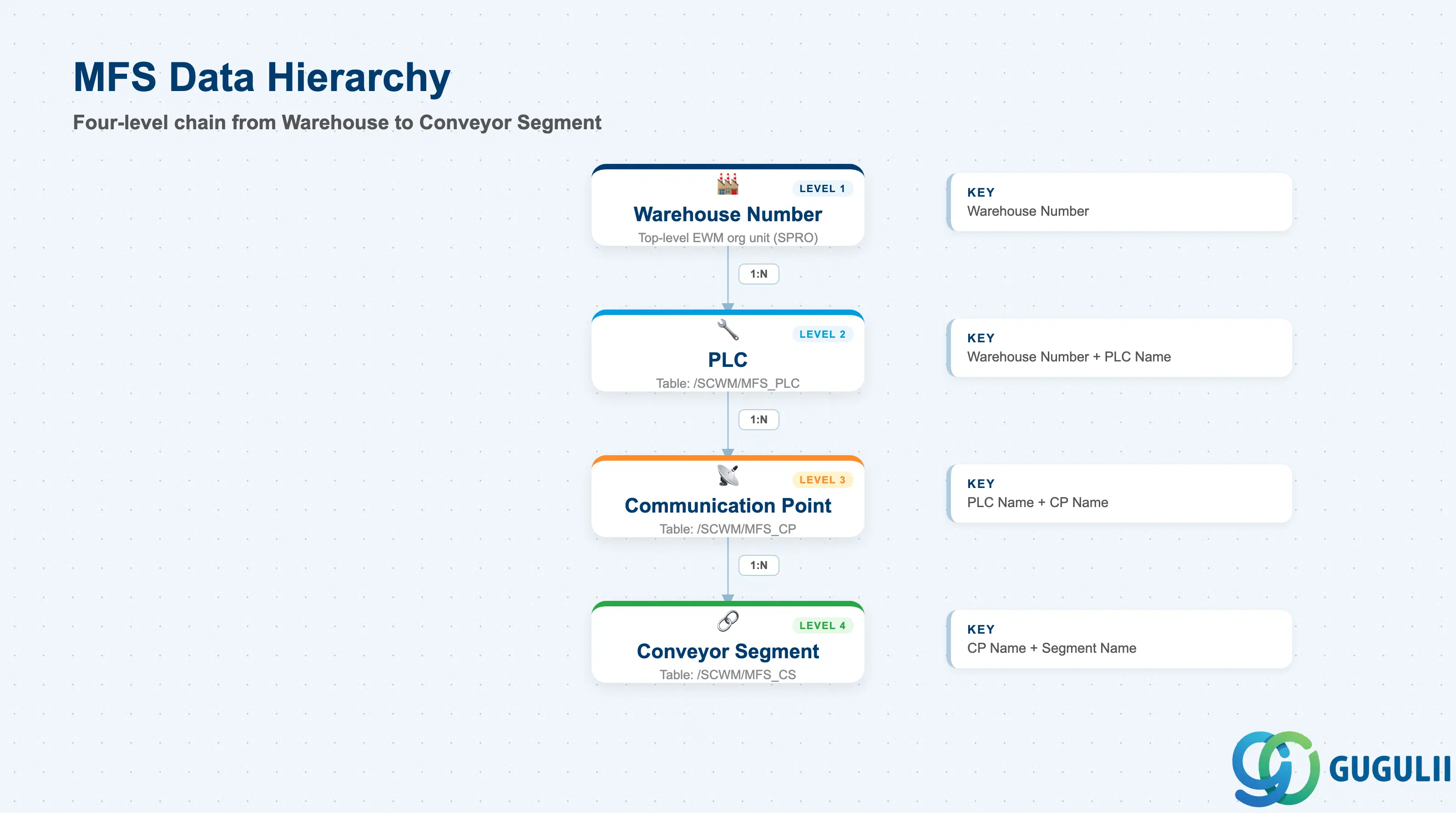
The PLC record belongs directly to the Warehouse Number — the top-level organizational unit in EWM. Below the PLC, the hierarchy always follows the same two-tier chain: Communication Point then Conveyor Segment. No plant or storage type scoping is applied at the PLC level.
Warehouse Number (e.g., WH01)
   │
   └── PLC  (/SCWM/MFS_PLC)
          │   Scope: Warehouse Number
          │   Key: Warehouse Number + PLC Name
          │
          └── Communication Point  (/SCWM/MFS_CP)
                 │   Scope: PLC
                 │   Key: PLC Name + CP Name
                 │
                 └── Conveyor Segment  (/SCWM/MFS_CS)
                        Scope: Communication Point
Key: CP Name + Segment Name| Org Level | Table | Primary Fields | Notes |
|---|---|---|---|
| Warehouse Number | (SPRO) | Warehouse Number | The PLC references the Warehouse Number set up in SPRO; one Warehouse Number can have multiple PLC records (one per physical controller) |
| PLC | /SCWM/MFS_PLC | PLC Name, IP Address, Port, Protocol, Communication Mode, Description | Defined once per physical controller device; all Communication Points under a PLC share its network endpoint |
| Communication Point | /SCWM/MFS_CP | CP Name, Telegram Type, Buffer Size, Timeout | Child of PLC; controls the logical channel over which specific telegram types flow |
| Conveyor Segment | /SCWM/MFS_CS | Segment Name, Source/Destination Bins, Activity Area | Grandchild of Communication Point; maps a physical conveyor section to EWM storage bins |
Key design decision: One PLC record per physical controller is standard. If a single controller manages two logically independent conveyor zones, separate Communication Points — not separate PLC records — are the correct modeling approach.
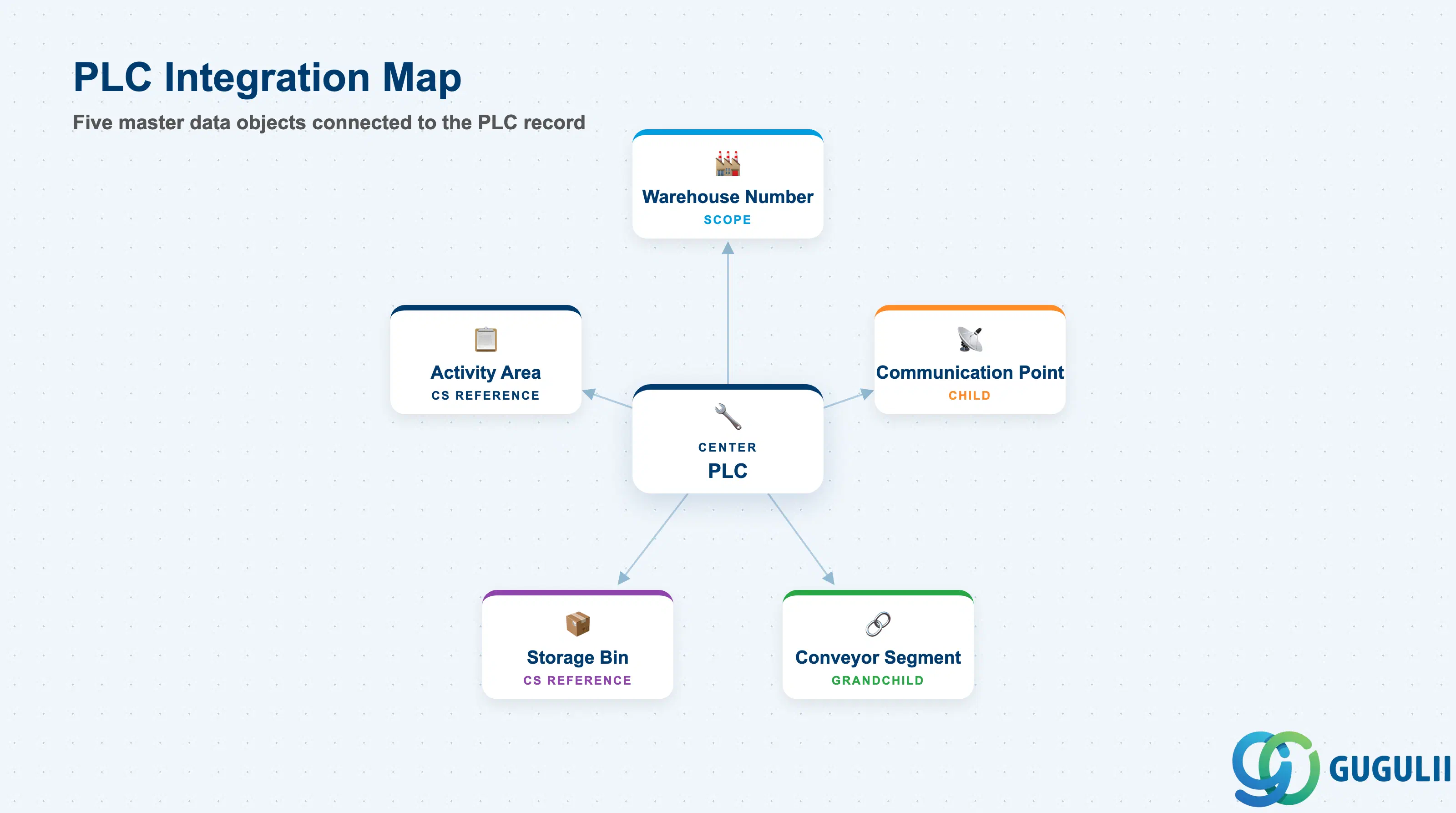
The PLC master record does not stand alone. It is the foundation of a three-tier MFS master data chain, and the Conveyor Segment at the bottom of that chain connects directly to core EWM logistics master data.
| Object | Relationship | Practical Notes |
|---|---|---|
| Warehouse Number | PLC is assigned to and scoped by the Warehouse Number | The Warehouse Number must be configured in SPRO before any PLC record can be created. In multi-warehouse deployments, each warehouse has its own independent PLC hierarchy. |
| Communication Point (EWM-A10-02) | Child of PLC; one PLC has 1:N Communication Points | Each Communication Point represents a logical channel (e.g., inbound lane telegrams vs. outbound sort telegrams). Creating the PLC first is a hard prerequisite for Communication Point creation. |
| Conveyor Segment (EWM-A10-03) | Grandchild of PLC via Communication Point | Conveyor Segments map physical conveyor sections to SAP storage bins and activity areas. The Segment is the object that triggers Transfer Order creation and MFS Queue events during automated picking and putaway. |
| Storage Bin (EWM-A04-02) | Referenced by Conveyor Segment | Source and destination bins on the Conveyor Segment must already exist in the warehouse structure. PLC configuration typically begins only after the physical bin layout has been finalized. |
| Activity Area (SPRO) | Referenced by Conveyor Segment (Wave Template context) | Activity Areas group storage bins for Wave Management. Conveyor Segments that serve automated picking areas must reference the correct Activity Area so that Wave Templates can route work to them. |
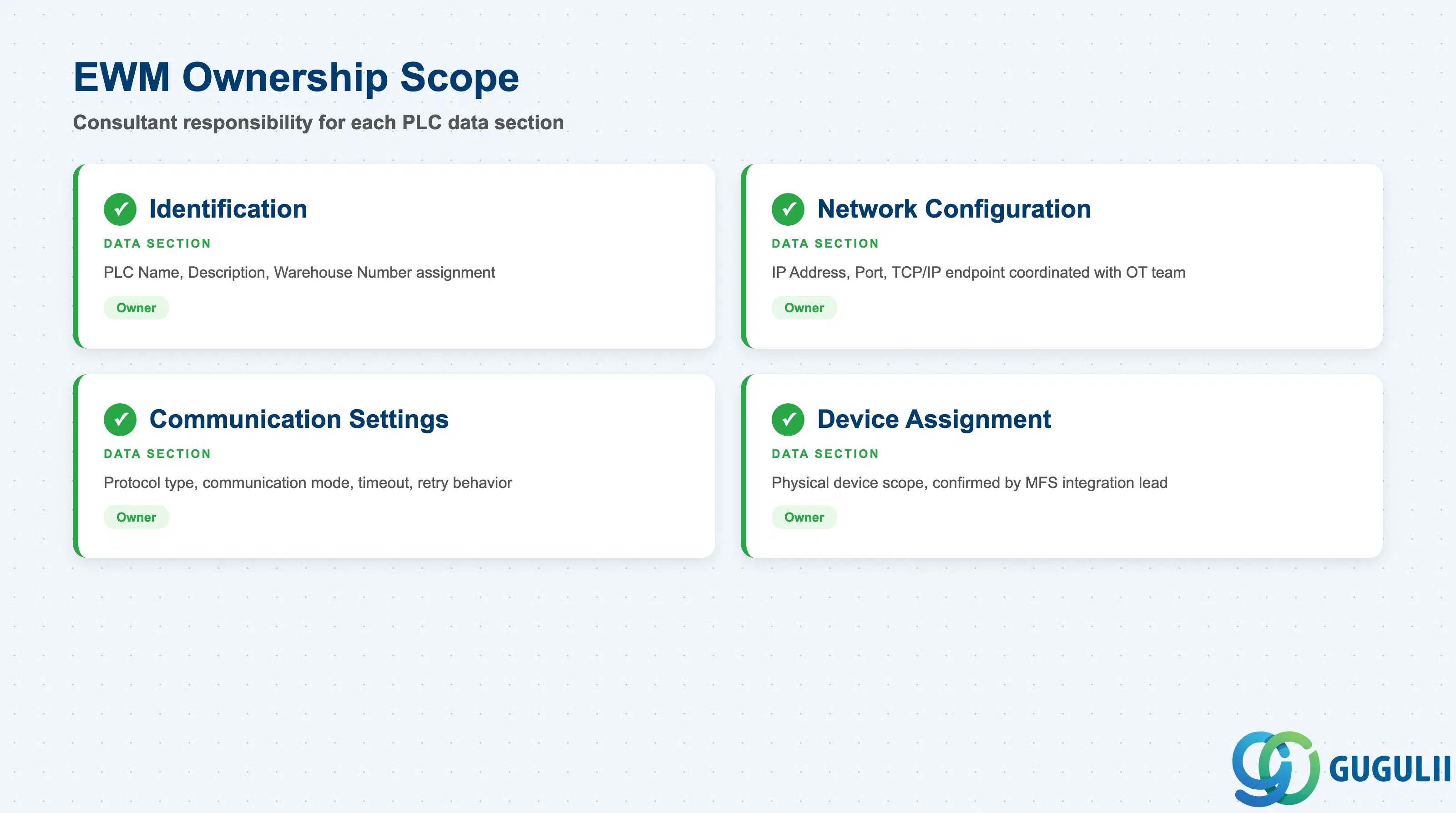
| Data Section | EWM Involvement | Notes |
|---|---|---|
| Identification | ◎ Owner | PLC Name, Description, Warehouse Number assignment |
| Network Configuration | ◎ Owner | IP Address, Port Number, and the underlying TCP/IP endpoint that EWM uses to contact the PLC; must be coordinated with the customer’s network / OT (Operational Technology) team |
| Communication Settings | ◎ Owner | Protocol type, communication mode (synchronous/asynchronous), timeout values, retry behavior |
| Device Assignment | ◎ Owner | Assignment of the PLC record to the physical device scope within the warehouse — functional confirmation by the MFS integration design lead |
Legend: ◎ = Owner / Critical, ○ = Direct involvement
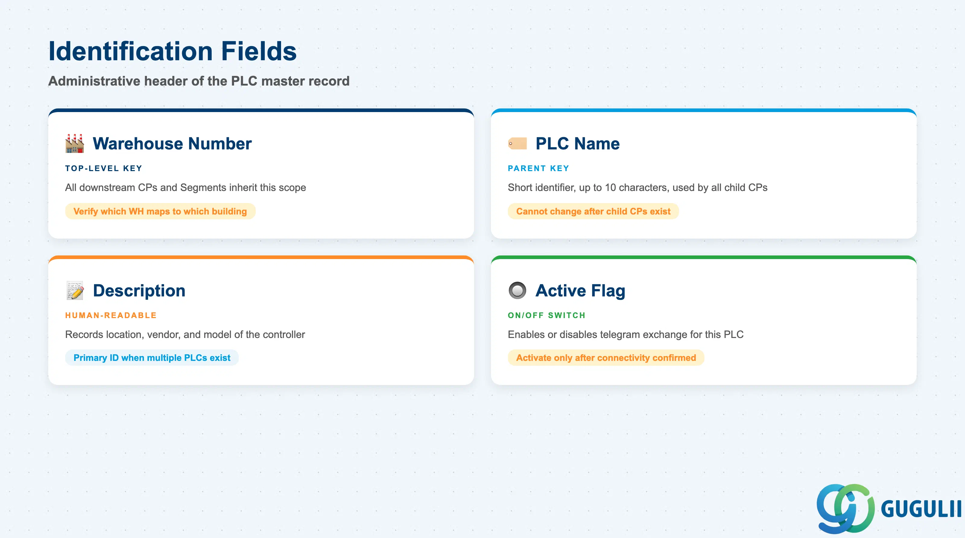
The Identification section is the administrative header of the PLC master record. Every field here must be agreed upon with the project team before setup begins, because the PLC Name is used as the foreign key throughout the Communication Point and Conveyor Segment records below it.
| Field | Description | Practical Usage |
|---|---|---|
| Warehouse Number | The EWM Warehouse Number this PLC belongs to | Acts as the top-level key. All downstream Communication Points and Conveyor Segments inherit this scope. In projects with multiple warehouses on the same EWM system, verify which Warehouse Number maps to which physical building before creating PLC records — reassignment after child records exist is not straightforward. |
| PLC Name | Short identifier for the PLC master record (typically up to 10 characters) | Used as the parent key on all child Communication Point records. Adopt a consistent naming convention early (e.g., PLC01, PLC-CONV-A, PLC-CRANE-1). The name cannot be changed after child Communication Points have been created without deleting and recreating the entire hierarchy. |
| Description | Free-text description of the physical controller | Use to record the physical location, equipment vendor, and model (e.g., “Siemens S7-1500 — Conveyor West Wing”). This field is the primary human-readable identifier when multiple PLCs exist under the same Warehouse Number. |
| Active Flag | Enables or disables telegram exchange for this PLC | Set to active only after network connectivity is confirmed and telegram templates have been tested in a development or quality system. Deactivating a PLC in production suppresses all MFS telegram traffic to that controller — useful as a controlled shutdown switch during planned equipment maintenance. |
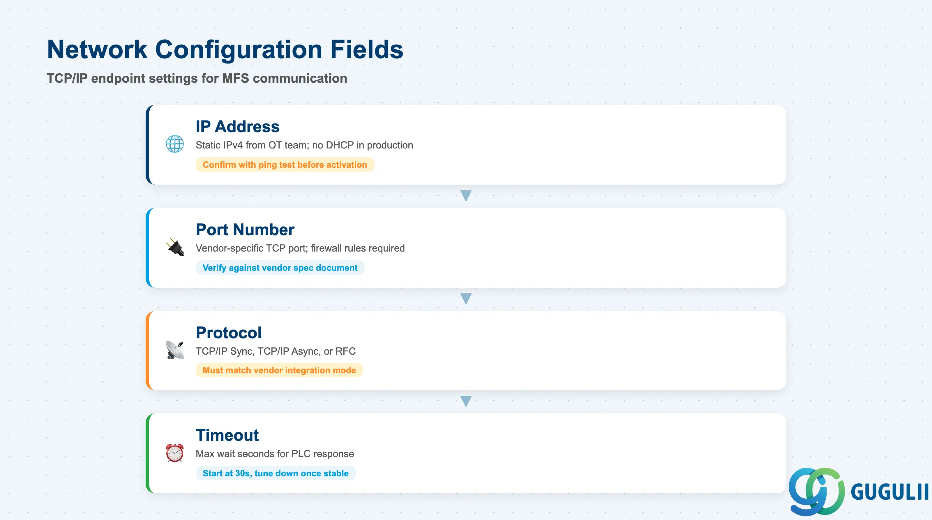
The Network Configuration section stores the TCP/IP endpoint that EWM’s MFS kernel uses to open a socket connection to the PLC. These values are provided by the customer’s OT (Operational Technology) or automation team — the EWM consultant is responsible for entering them correctly but does not define them.
| Field | Description | Practical Usage |
|---|---|---|
| IP Address | IPv4 address of the PLC’s network interface | Provided by the customer’s OT team. Must be a static IP; DHCP-assigned addresses for PLCs are not supported in production MFS environments because EWM caches the connection endpoint and does not re-resolve dynamically. Confirm the address with a network ping test from the EWM application server before activating the PLC record. |
| Port Number | TCP port the PLC listens on for MFS telegram traffic | Agreed between the SAP MFS implementation team and the PLC vendor. Common values vary by vendor and installation; always verify against the PLC vendor’s integration specification document. Firewall rules in the OT network must permit traffic from the EWM application server’s IP to this port. |
| Protocol | Communication protocol: TCP/IP Synchronous, TCP/IP Asynchronous, or RFC | Determines the telegram exchange model (see Section 1.2). Must match the PLC vendor’s supported integration mode. For ASRS crane controllers that expose an RFC interface, select RFC and configure the RFC destination separately in SM59. |
| Timeout (seconds) | Maximum wait time for a PLC response before EWM raises a communication error | Set conservatively during initial go-live (e.g., 30 seconds) and tune downward once stable telegram round-trip times are observed. A timeout that is too short causes false communication alarms; a timeout that is too long causes Transfer Orders to hang and block downstream MFS Queue processing. |
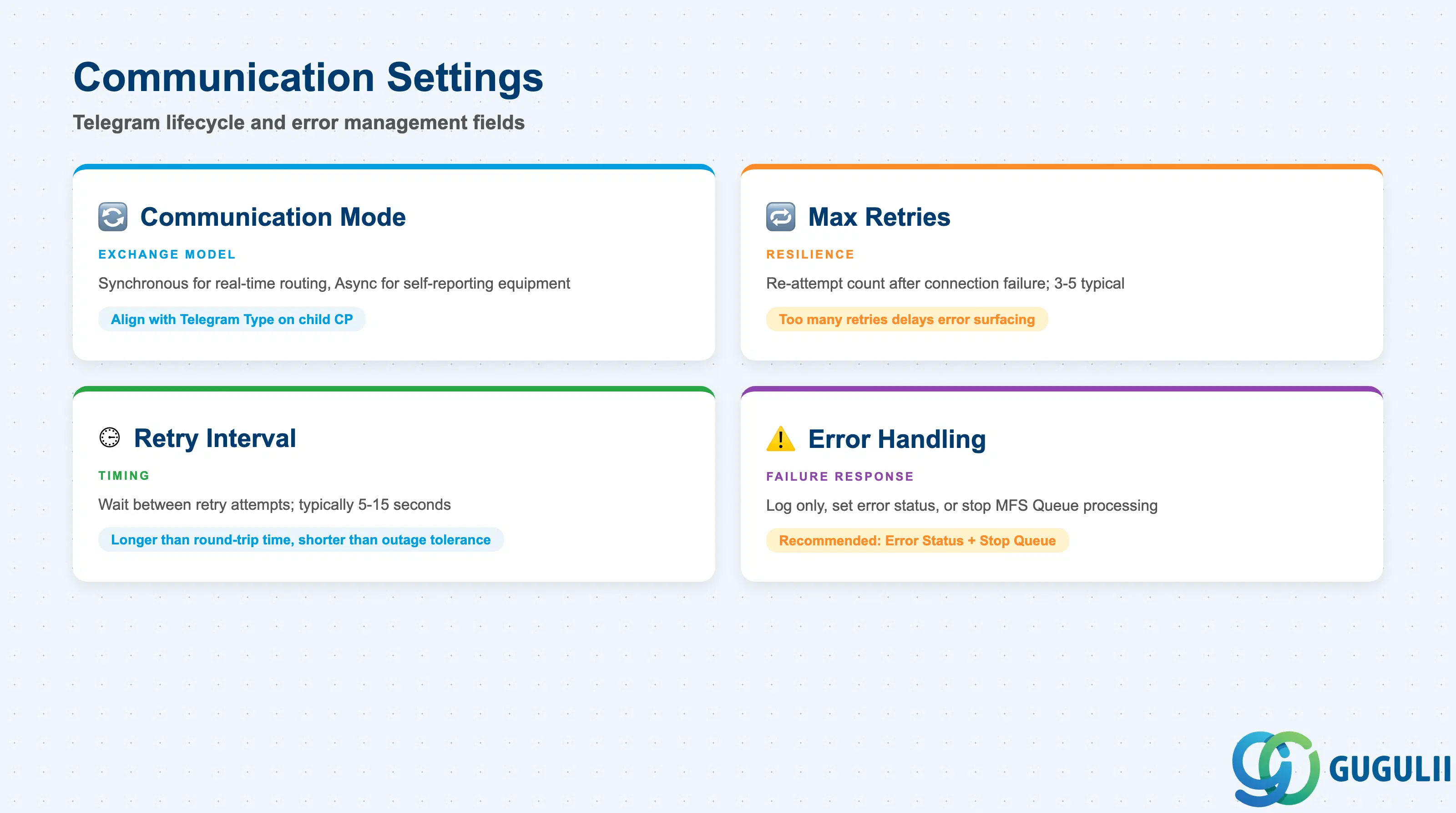
Communication Settings control how EWM manages the telegram exchange lifecycle — what happens when a connection fails, how many retry attempts are made, and how errors are surfaced to warehouse operators.
| Field | Description | Practical Usage |
|---|---|---|
| Communication Mode | Synchronous or Asynchronous message exchange (see Section 1.2) | For sorters and divert gates where real-time routing decisions are needed, Synchronous mode ensures EWM waits for the PLC’s OK before routing the handling unit. For conveyors that self-report completion, Asynchronous mode reduces EWM processing overhead. The mode must be aligned with the Telegram Type defined on the child Communication Point. |
| Max Retries | Number of times EWM re-attempts to send a telegram after a connection failure | A value of 3 to 5 is typical for production environments. Too few retries causes excessive communication alarms from transient network glitches; too many retries delays error surfacing and can cause MFS Queue backlogs if the PLC is genuinely offline. |
| Retry Interval (seconds) | Wait time between retry attempts | Set longer than the network round-trip time but short enough to allow rapid recovery from transient outages. Typically 5 to 15 seconds. |
| Error Handling Mode | Defines the system response when all retries are exhausted: log only, set PLC to error status, or stop MFS Queue processing | In high-throughput automated warehouses, the recommended mode is “Set PLC to Error Status and Stop Queue” to prevent accumulation of unprocessed telegrams. Operations teams must be trained to monitor the PLC status monitor (/SCWM/MFS) and reset the error status after the physical connection is restored. |
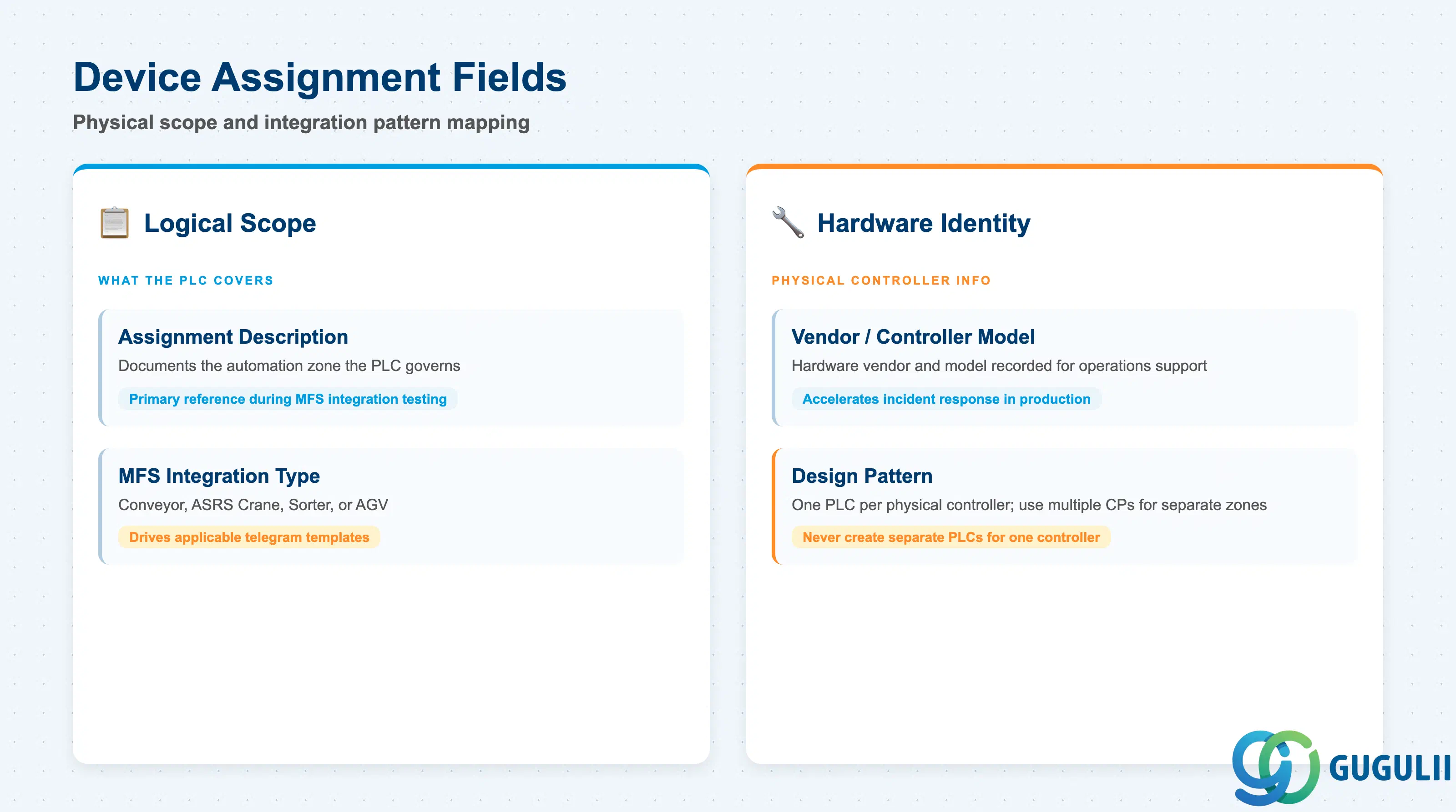
Device Assignment defines how the PLC master record maps to the physical automation scope within the warehouse. Unlike the network and protocol fields — which are point-to-point configuration — device assignment captures the logical boundary of what the controller is responsible for.
| Field | Description | Practical Usage |
|---|---|---|
| Assignment Description | Free-text field describing the physical scope this PLC covers | Document the automation zone the PLC governs (e.g., “Inbound conveyor loop — Aisles 1 through 6, West building”). During MFS integration testing, the assignment description is the primary reference for identifying which EWM Conveyor Segments should be routed to which physical controller. |
| MFS Integration Type | Categorizes the integration pattern: Conveyor-based, ASRS Crane, Sorter, or AGV (Automated Guided Vehicle) | Drives which telegram templates are applicable for the Communication Points under this PLC. Conveyor-based PLCs use standard MFS conveyor telegrams; ASRS cranes typically use task-based telegrams with position codes; AGV systems have vendor-specific telegram formats that may require custom BAdI implementation. |
| Vendor / Controller Model | Informational field for the hardware vendor and controller model name | Not system-enforced, but essential for ongoing operations and support. When a communication error is raised in production, the first step is to consult the PLC vendor’s troubleshooting guide — having the vendor and model recorded on the master record accelerates incident response. |
| ID | Category | Title |
|---|---|---|
| ewm-001 | Overview | What is SAP EWM? |
| ID | Category | Title |
|---|---|---|
| ewm-b01 | Overview | SAP EWM Transactions: Process Flow, Hierarchy & Relationships |