Title here
Summary here

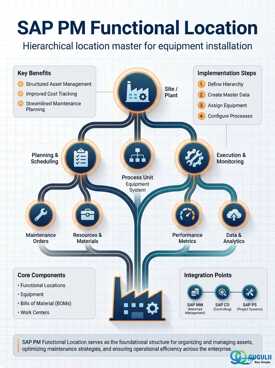
The Functional Location (FL) is the master data object that defines where technical objects are installed in an SAP PM environment. It establishes a hierarchical location structure — from plant down to individual process positions — and serves as the anchor point for Equipment, Measuring Points, Maintenance Plans, and the entire PM cost tracking chain. Before any equipment can be maintained in SAP PM, the location hierarchy that will house it must be designed and created. This article covers FL concepts applicable across modules (Part 1) and then provides PM-specific field-level detail (Part 2).
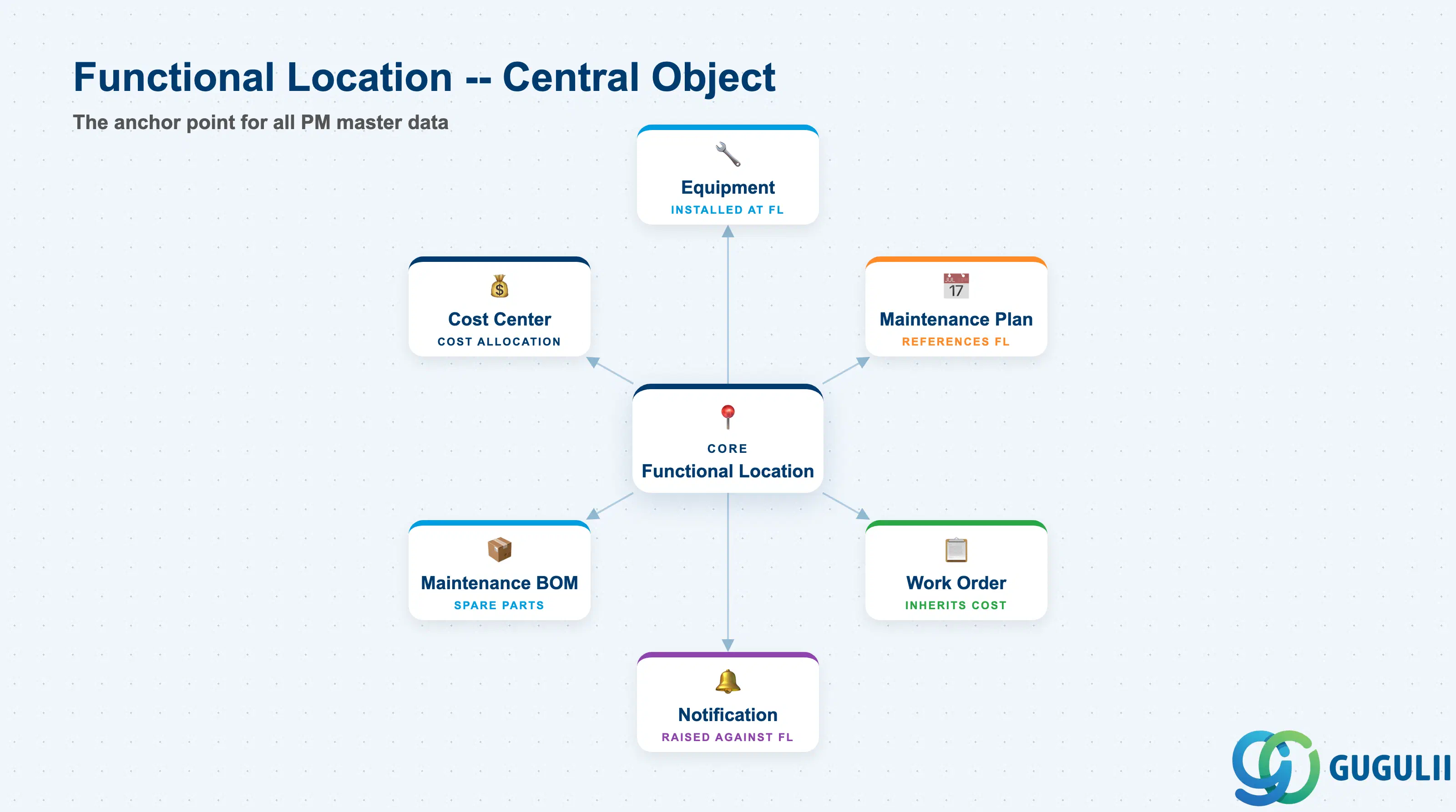
The Functional Location is a location-based master data object that represents where a technical object is or will be installed. Unlike Equipment — which represents a physical, serialized asset — a Functional Location describes a fixed position in the plant or facility. Equipment is installed at a Functional Location; the location remains even if the equipment is swapped out or decommissioned.
| Aspect | Details |
|---|---|
| Role | Defines the hierarchical installation location structure; anchors Equipment, costs, and maintenance history to fixed positions |
| Modules using it | PM (primary owner — location hierarchy, cost collection, maintenance planning), FI/CO (cost center assignment for maintenance cost allocation), MM (spare parts BOM via FL BOM) |
| Transactions | IL01 (Create) / IL02 (Change) / IL03 (Display) / IH01 (Display FL Structure) / IL05 (Change Multiple FL) |
| Key Tables | IFLOT (FL master data) / IFLOTX (FL descriptions) / IFLOS (FL structure — parent-child relationships) / ILOA (FL location and account assignment data) |
| S/4HANA note | FL data model is unchanged from ECC. Structure Indicator remains the central design decision. Fiori apps “Manage Functional Locations” (F2858) and “Display Functional Location Structure” are available alongside classic transactions. |
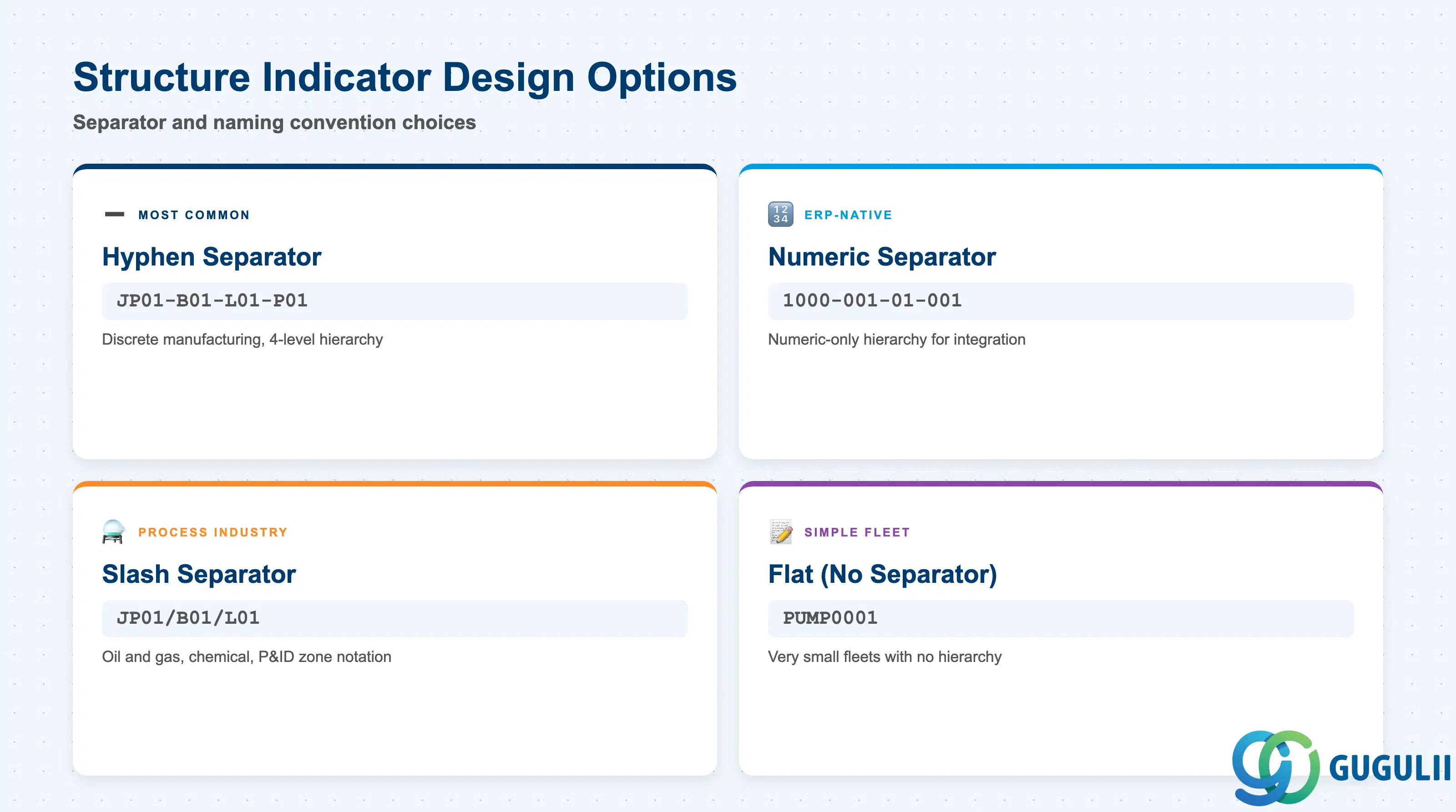
The Structure Indicator is the most consequential design decision in an FL implementation. It defines the separator character, the number of hierarchy levels, and the character length of each level — and it cannot be changed after FL records are created without data migration. Getting it wrong at go-live is costly.
| Design Dimension | Code / Example | Use Case | Key Behavior |
|---|---|---|---|
| Separator: hyphen | JP01-B01-L01-P01 | Plant − Building − Line − Position (4 levels) | Most common in discrete manufacturing; readable and sortable |
| Separator: dash with leading zeros | 1000-001-01-001 | Numeric-only hierarchy for ERP-native numbering | Better integration with PP line numbering; harder for operators to read |
| Separator: slash | JP01/B01/L01 | Process plants (oil & gas, chemical) with 3-level zone structures | Common in process industries; aligns with P&ID zone notation |
| Flat (no separator) | PUMP0001 | Simple environments with no hierarchy needed | Only appropriate for very small fleets; loses location-grouping capability |
Design principle: Design the Structure Indicator before any go-live data entry. Changing the separator character or level length after FL records exist requires a custom data migration program. Always involve the maintenance manager and IT architect in this decision during blueprint.
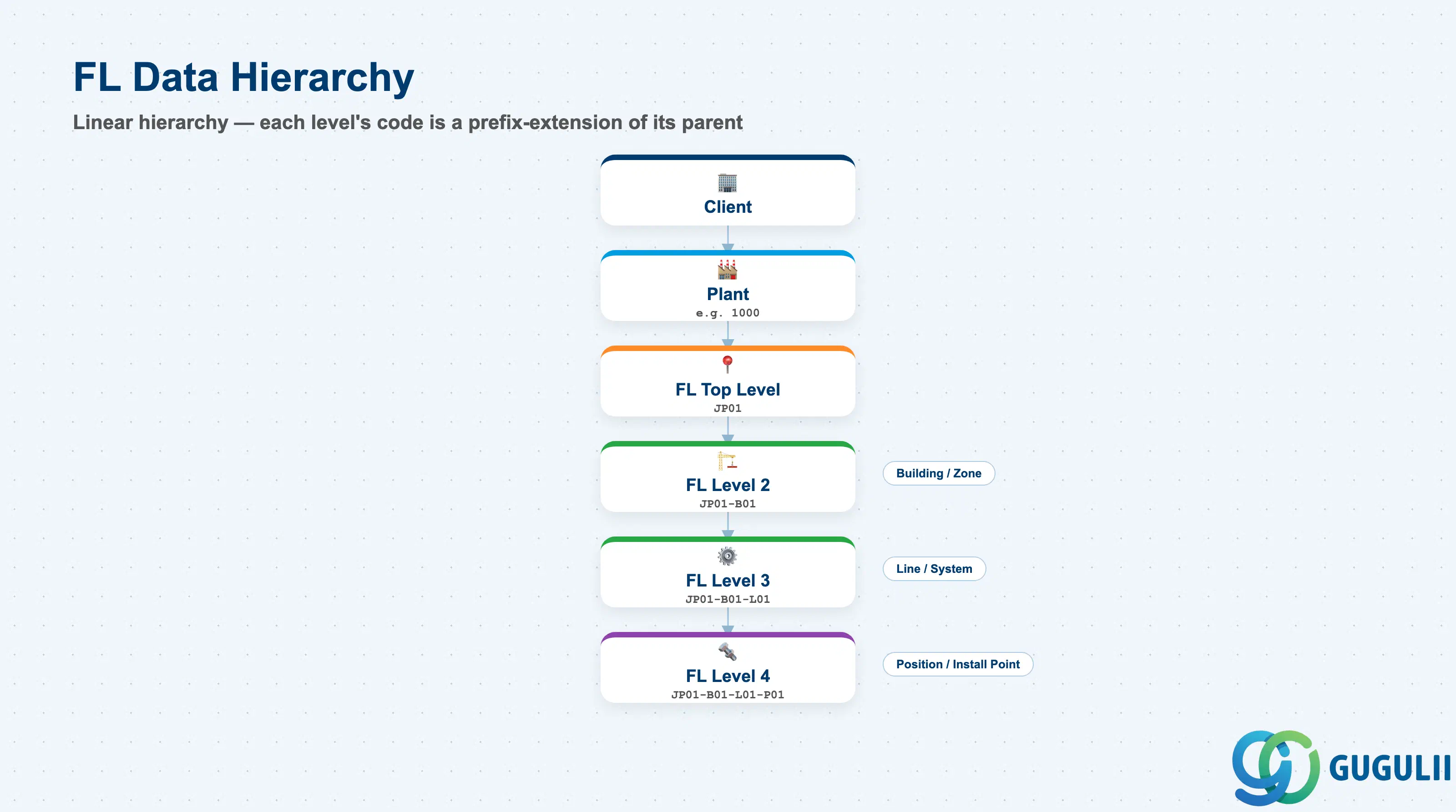
The Functional Location carries data at two organizational levels: the plant level (via account assignment in ILOA) and the individual FL node level. Within the FL node itself, data is organized into views (tabs) that parallel the Equipment master structure.
Client
   │
   └── Plant (e.g., 1000 — Tokyo Plant)
          │
          └── Functional Location — Top Level (e.g., JP01)
                 │    Table: IFLOT (master data), IFLOTX (text), ILOA (account assignment)
                 │
                 ├── Functional Location — Level 2 (e.g., JP01-B01)
                 │      Building / Zone / Area
                 │
                 ├── Functional Location — Level 3 (e.g., JP01-B01-L01)
                 │      Production Line / System
                 │
                 └── Functional Location — Level 4 (e.g., JP01-B01-L01-P01)
                        Process Position / Installation Point
← Equipment is installed here| Org Level | Table | Primary Fields | Notes |
|---|---|---|---|
| FL Node (all levels) | IFLOT | FL label, description, category, sort field, ABC indicator, construction year | One IFLOT row per FL node. The FL label is the key — it encodes the hierarchy position via the Structure Indicator |
| FL Description | IFLOTX | Short text (30 chars), long text | Language-dependent; maintain at least the logon language |
| FL Structure | IFLOS | Superior FL (parent), hierarchy level | Governs the parent-child relationship used by IH01 and cost roll-up |
| Account Assignment | ILOA | Plant, Location, Room, Cost center, WBS element, Asset | Assigned at each FL node; inherited by Equipment installed there unless overridden at Equipment level |
Key design decision: Assign Cost Centers at a meaningful hierarchy level (typically line or system level). Assigning at the lowest position level creates excessive CO master data; assigning only at plant level loses cost granularity for maintenance analysis by line.
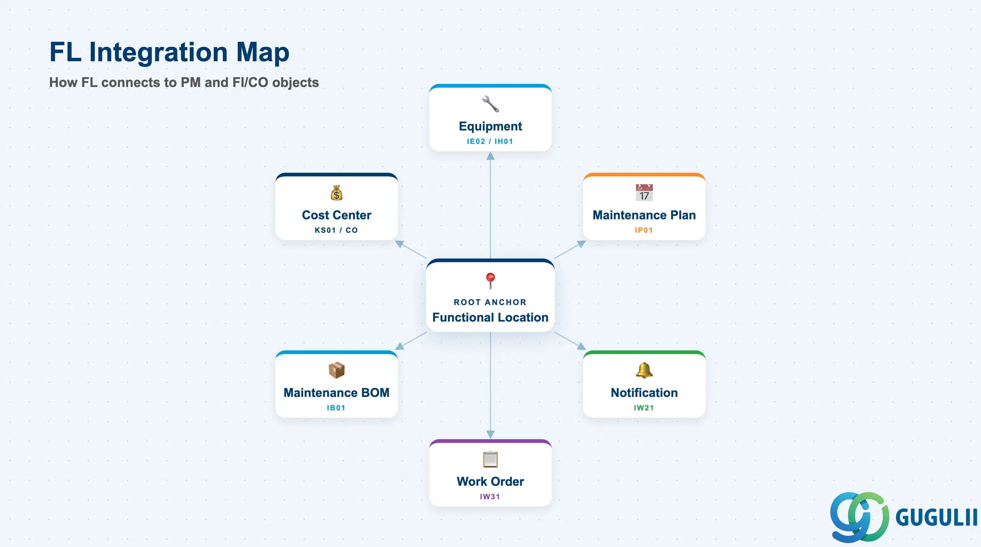
The Functional Location does not stand alone. It is the root anchor for the entire PM object network — almost every PM master data object either directly references an FL or inherits data from it.
| Object | Relationship | Practical Notes |
|---|---|---|
| Equipment | Equipment is installed at a Functional Location | When Equipment is installed (IE02 / IH01), it inherits the FL’s account assignment (Cost Center, WBS, Asset) unless explicitly overridden. Moving Equipment between FLs automatically re-routes maintenance costs to the new FL’s cost assignment. |
| Maintenance Plan (IP01) | Maintenance Plan references FL as the reference object | Time-based and counter-based plans can be created for an FL directly — useful for location-based maintenance (e.g., fire suppression system at JP01-B01) regardless of which specific equipment is installed. |
| Notification (IW21) | Notifications can be raised against an FL | When a defect is reported at a location without a known equipment number, the FL is used as the reference object. The Work Order inherits the FL’s account assignment for cost posting. |
| Maintenance BOM (IB01) | FL BOM lists the spare parts associated with a location | Usage “3” (PM BOM). Enables automatic component proposals in Work Orders created against the FL. Distinct from Equipment BOM — use FL BOM for location-specific consumables (filters, lubricants) and Equipment BOM for equipment-specific parts. |
| Class / Characteristic (CL01/CT04) | FL can be assigned to classes for attribute management | Enables classification-based FL search (e.g., find all locations with “hazardous zone” characteristic = “Zone 1”). Required when regulatory compliance demands structured attribute documentation on locations. |
| Cost Center (CO) | FL account assignment links maintenance costs to CO | All Work Orders settled against an FL post costs to the assigned Cost Center. PM cost reporting by plant area, line, or zone depends entirely on a well-designed FL cost center assignment strategy. |
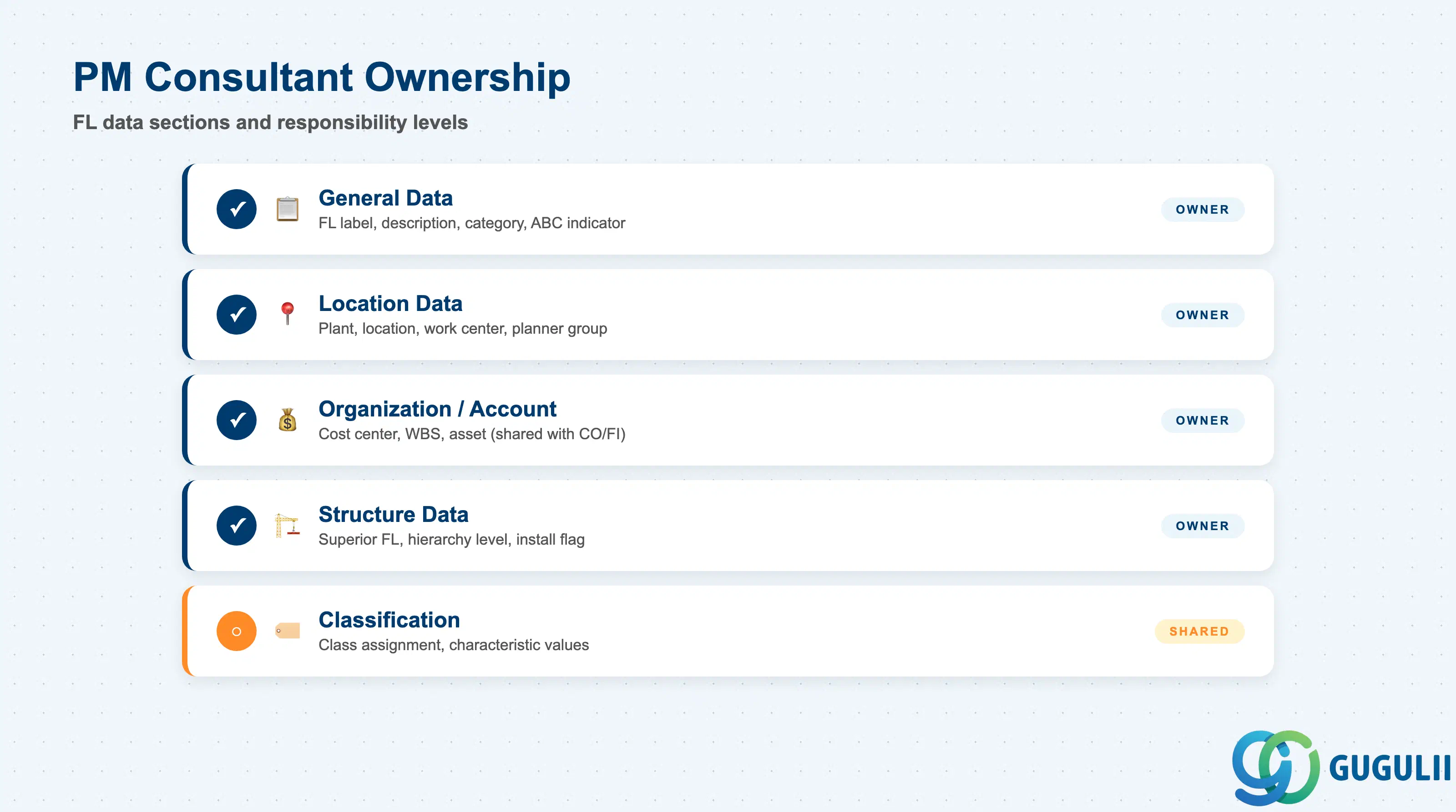
| Data Section | PM Involvement | Notes |
|---|---|---|
| General Data | ◎ Owner | FL label, description, category, ABC indicator, construction year |
| Location Data | ◎ Owner | Plant, location room, plant section, work center, planner group |
| Organization / Account Assignment | ◎ Owner (shared with CO/FI) | Cost center, WBS element, asset, business area |
| Structure Data | ◎ Owner | Superior FL, hierarchy level, installation allowed flag |
| Classification | ○ Shared with PM Admin | Class assignment and characteristic values; typically PM Admin configures, PM consultant designs the schema |
Legend: ◎ = Owner / Critical, ○ = Direct involvement
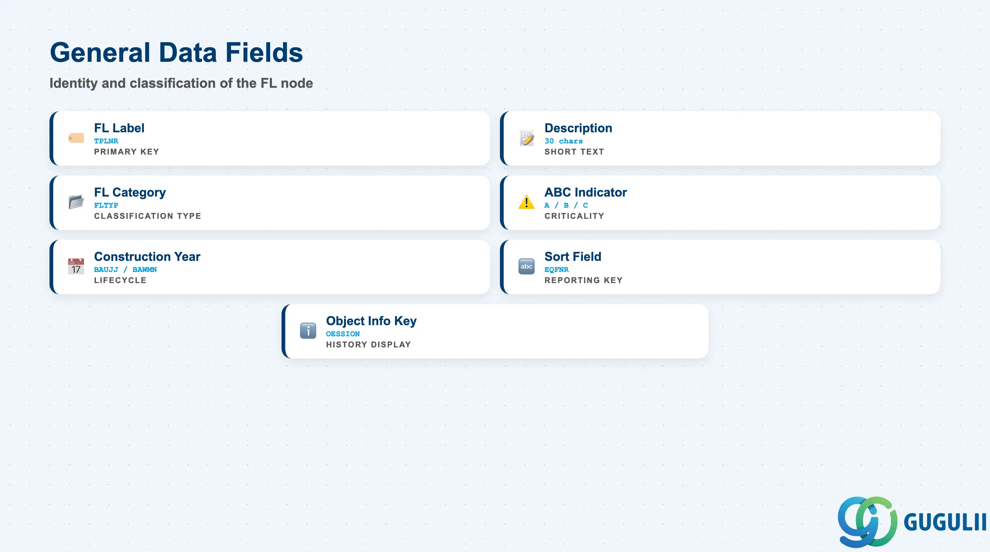
General Data defines the identity and classification of the Functional Location node. These fields are set at creation and form the basis for all FL-level reporting and filtering.
| Field | Description | Practical Usage |
|---|---|---|
| Functional Location (TPLNR) | The FL label — the primary key | Encodes the hierarchy position based on the Structure Indicator. Once created, the label cannot be changed (a new FL must be created and equipment re-installed). Follow the naming convention agreed in blueprint without exception — inconsistencies create permanent reporting anomalies. |
| Description | Short text for the FL (30 chars) | Should describe the location’s purpose clearly enough for a technician unfamiliar with the site. Example: “Body Shop Weld Line 1 Robot Pos 3.” Avoid abbreviations only the original configurator understands. |
| Functional Location Category | Classification category for the FL type | Controls which views and data entry screens are relevant. Common categories: F (Functional Location standard), or customer-defined categories per hierarchy level (e.g., category “P” for Plant level, “L” for Line level). Design categories during blueprint to enable level-specific field control. |
| ABC Indicator | Criticality classification (A/B/C) | A = High criticality (production-critical, safety-critical). B = Medium. C = Low. Drives maintenance priority rules and reporting. Should reflect the business impact of a failure at this location, not just the cost of the equipment installed there. |
| Construction Year / Month | Year and month of construction or commissioning | Used in asset lifecycle reporting and for computing age-based maintenance triggers. For existing facilities, populate from as-built documentation or facility records. |
| Sort Field | Free-text sort key for reporting | Enables alternative sorting in FL lists (IH01, IL05). Commonly used to store legacy system identifiers or plant engineering drawing references for cross-reference lookups during cutover. |
| Object Information Key | Controls which data is displayed in the object information pop-up | Determines which historical data (notifications, orders, measuring docs) is shown when the FL is referenced in a transaction. Configure during blueprint to show the most operationally relevant history. |
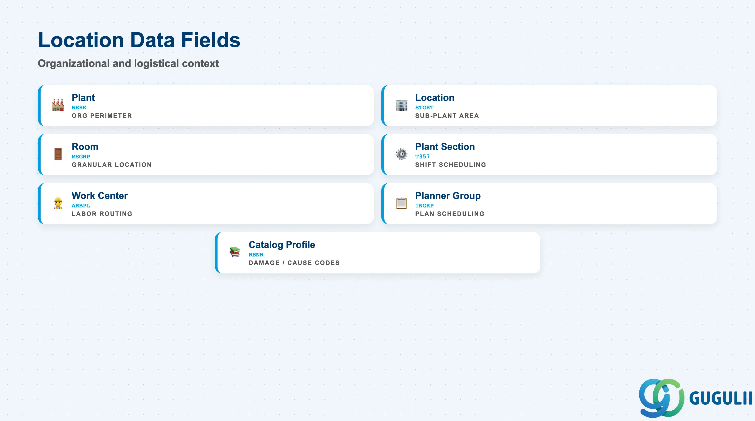
Location Data connects the Functional Location to the organizational and logistical context of the plant. These fields determine who is responsible for maintenance at this location and how work orders are routed.
| Field | Description | Practical Usage |
|---|---|---|
| Plant (WERK) | The plant to which the FL belongs | All FLs under a top-level node share the same plant. The plant determines the PM organizational perimeter — inter-plant maintenance requires careful cost allocation design. |
| Location | Sub-plant location (building, bay, zone) | Free-text descriptor at the plant level (configured in Customizing). Example: “Building A,” “North Wing.” Provides a secondary grouping layer below plant for reporting when the FL hierarchy itself is too granular for management dashboards. |
| Room | Room within the location | Most granular physical location descriptor. Used in facilities management scenarios and regulated industries where room-level audit trails are required. |
| Plant Section | Operational area within the plant | Links to the Plant Section object in Customizing (table T357). Used for shift-based maintenance scheduling — the Plant Section drives which crew is responsible and which work center receives the notification. |
| Work Center (ARBPL) | Responsible maintenance work center | The default work center responsible for maintenance work at this location. Inherited by Equipment installed here unless overridden. Drives labor cost routing in Work Orders. In Japan-targeted implementations, align work center codes with the maintenance department organizational structure agreed during blueprint. |
| Planner Group | Maintenance planning group | Identifies the maintenance planner responsible for scheduling work at this location. Used in Maintenance Plan scheduling (IP10) and in notification routing. Establish a clear planner group assignment policy during blueprint — unclear assignment causes backlogs to accumulate unnoticed. |
| Catalog Profile | Damage/cause/activity catalog assignment | Controls which notification catalogs (damage codes, cause codes, activity codes) are available when a notification is raised against this FL. Align catalog profiles with equipment type categories to ensure meaningful failure analysis data. |
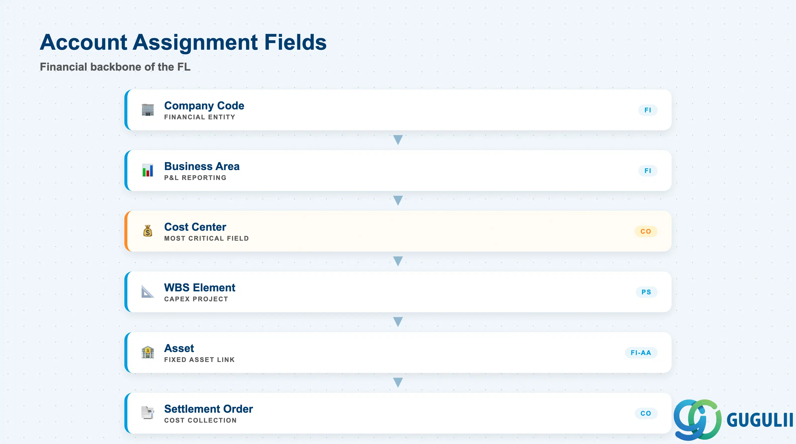
The account assignment section is the financial backbone of the Functional Location. Fields here determine where maintenance costs flow in FI and CO, and they are inherited by all Equipment installed at the FL unless overridden.
| Field | Description | Practical Usage |
|---|---|---|
| Company Code | Financial company code | Must be consistent with the plant’s company code assignment. For multi-company implementations, confirm with FI that the cost center and FL plant assignments are aligned to the same company code. |
| Business Area | Financial reporting unit | Used for business area-based P&L reporting. In manufacturing environments, maps to a production segment (e.g., Body Shop, Paint Shop). Required when the client uses business area financial statements. |
| Cost Center (KOSTL) | CO cost center that receives maintenance costs | The most critical account assignment field. All Work Orders settled against this FL post to this cost center. For hierarchical cost reporting, assign cost centers at the line or system level — not at individual position level. Changes to the cost center take effect from the next period; historical orders remain on the original cost center. |
| WBS Element | Project-based cost assignment | Assign when maintenance costs should be tracked against a capital project (CAPEX) rather than a cost center (OPEX). Typical use: new facility commissioning or major overhaul projects. Should be left blank for routine corrective and preventive maintenance. |
| Asset (Acquisition) | Fixed asset number linked to the location | Populated when the location itself is treated as a fixed asset (common for civil structures). For most equipment-level asset tracking, the Asset field on the Equipment master is used instead. Confirm the asset assignment strategy with FI-AA during blueprint. |
| Settlement Order | Internal order for maintenance cost collection | An alternative to cost center assignment — maintenance costs accumulate on the internal order for periodic settlement to cost centers or profitability segments. Used when granular cost tracking is needed beyond what cost center level allows. |
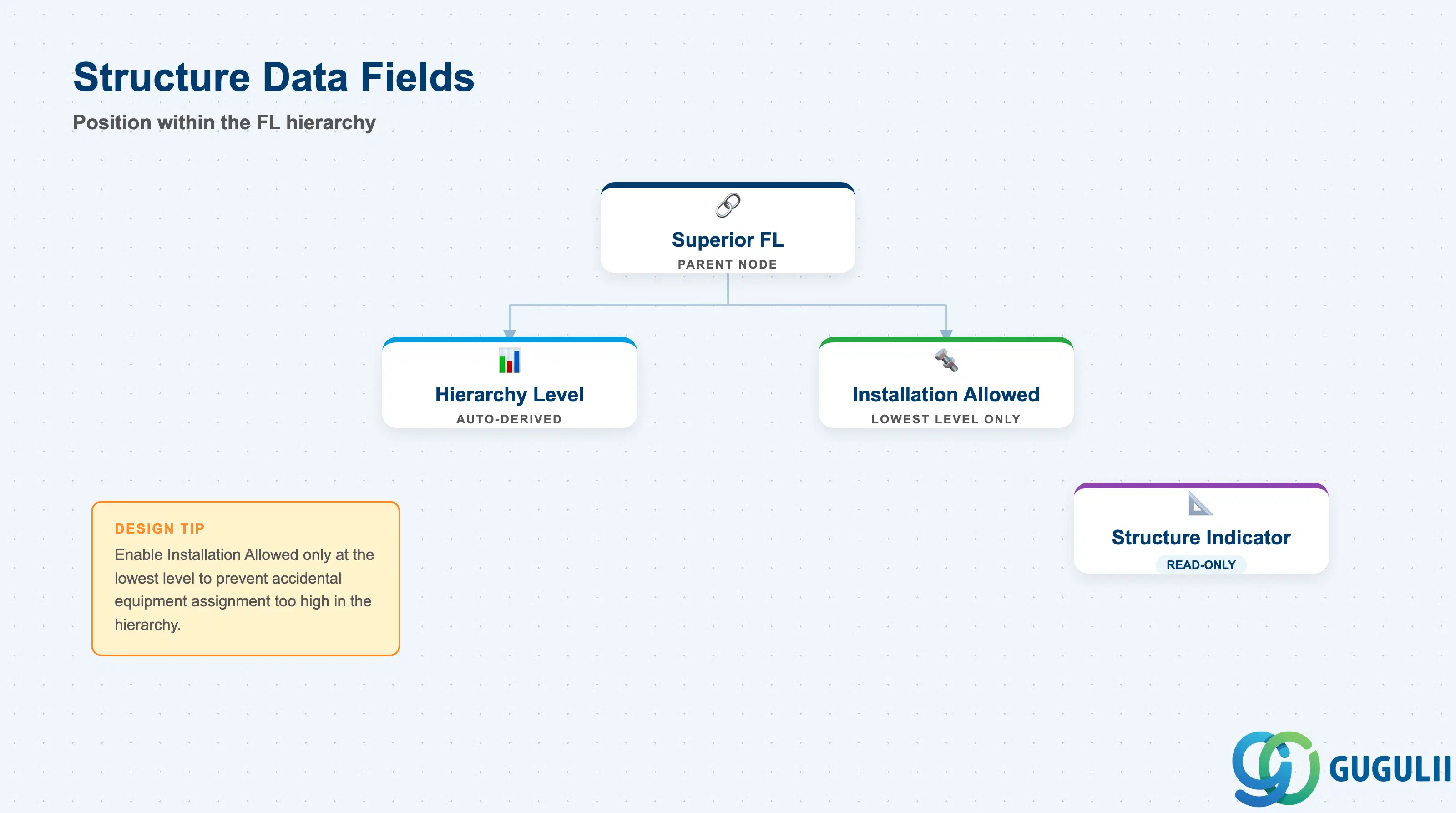
Structure Data governs the position of the FL node within the overall hierarchy. These fields are set by the Structure Indicator design and the parent-child assignment made at creation time.
| Field | Description | Practical Usage |
|---|---|---|
| Superior Functional Location | Parent FL label | Defines the parent node in the FL hierarchy. The system derives this automatically from the FL label when the Structure Indicator separator is used consistently. If the FL label naming convention is broken, the parent-child relationship must be set manually — a sign of a naming convention problem that should be corrected. |
| Hierarchy Level | Numeric level within the FL tree | Automatically derived from the separator position in the FL label. Level 1 = plant level; each separator adds a level. Used in IH01 drilldown navigation and in BW/Fiori FL hierarchy reporting. |
| Installation Allowed | Flag permitting Equipment installation at this node | When checked, Equipment can be installed at this FL. Typically enabled at the lowest hierarchy level (position level). Disable at intermediate levels (e.g., building level) to prevent Equipment from being accidentally assigned too high in the hierarchy, losing cost granularity. |
| Structure Indicator (display only) | Shows the Structure Indicator assigned to this FL | Read-only in the FL master. Set at FL category level in Customizing. Confirms which naming convention governs this FL. If an FL appears in an unexpected hierarchy position, check that its category uses the correct Structure Indicator. |
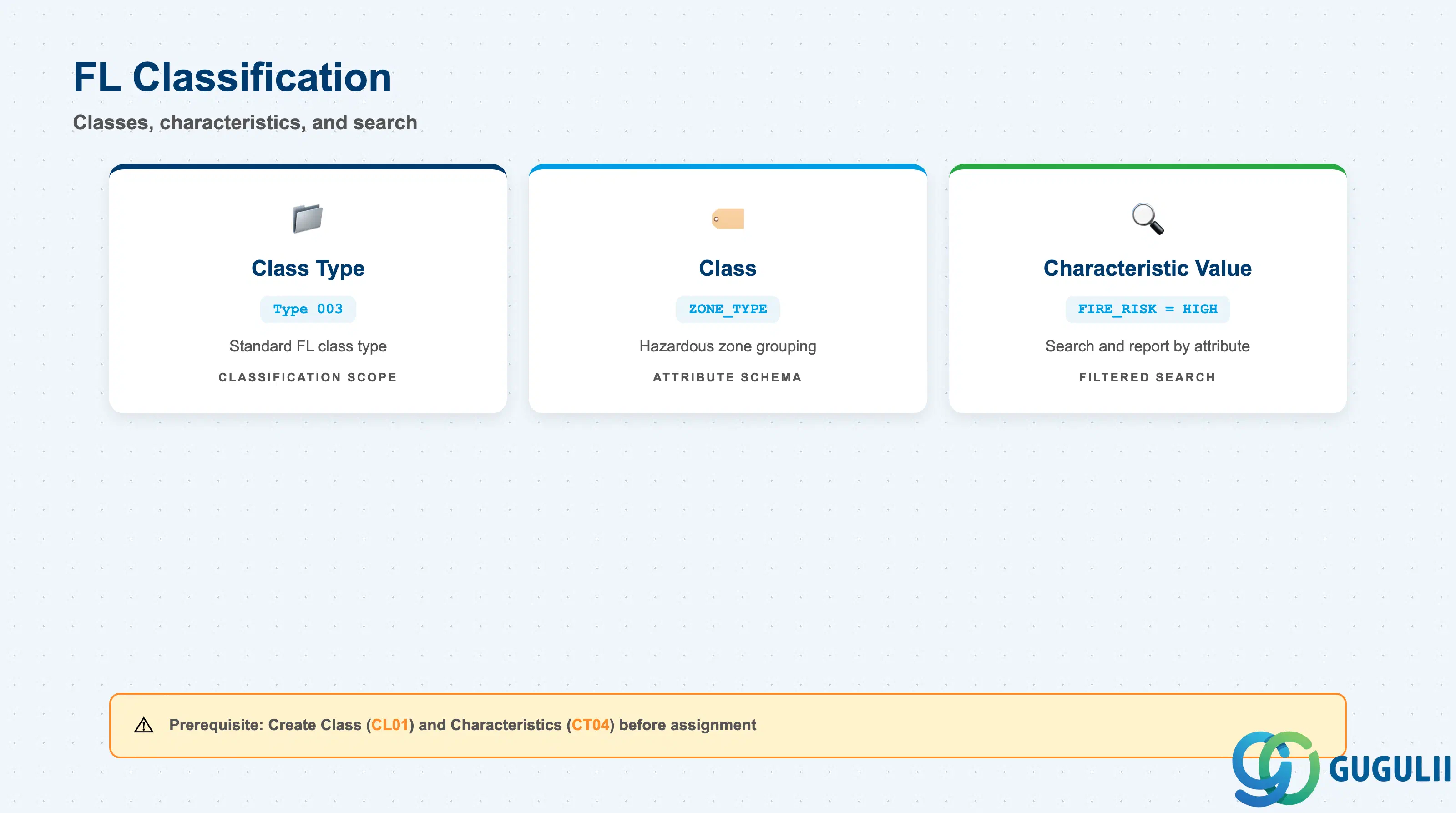
Classification allows the Functional Location to be assigned to one or more Classes, with Characteristics capturing attributes not covered by standard FL fields. The PM consultant designs the classification schema during blueprint; the PM Administrator configures and maintains it.
| Field | Description | Practical Usage |
|---|---|---|
| Class Type | Type of class used for FL classification | Class Type 003 (Functional Location) is the standard type for FL classification. Confirm with the PM classification Customizing team that Type 003 is activated for the relevant class. |
| Class | Class assigned to the FL | Links the FL to a characteristic schema. Example: class “ZONE_TYPE” to categorize FLs by hazardous zone level (IECEx Zone 0 / Zone 1 / Zone 2). Multiple classes can be assigned to a single FL. |
| Characteristic Value | Value assigned to a class characteristic | Enables search and reporting by attribute. Example: characteristic “FIRE_RISK” = “HIGH” allows mass listing of all high fire-risk locations via IL05 or classification search (CL30N). Values are validated against the characteristic definition (CT04). |
Prerequisite: The Class and Characteristics must be created (CL01 / CT04) and the class must be activated for Class Type 003 before assignment is possible in the FL master.
| ID | Category | Title |
|---|---|---|
| pm-001 | Overview | What is SAP PM? |
| ID | Category | Title |
|---|---|---|
| pm-a01 | Overview | SAP PM Master Data: Overview, Hierarchy & Relationships |
| pm-a02-01 | Master Data | SAP PM Functional Location 📍 |
| pm-a02-02 | Master Data | SAP PM Equipment |
| pm-a03-01 | Master Data | SAP PM Class |
| pm-a03-02 | Master Data | SAP PM Characteristic |
| pm-a04-01 | Master Data | SAP PM Measuring Point |
| pm-a05-01 | Master Data | SAP PM Work Center |
| pm-a06-01 | Master Data | SAP PM Material Master |
| pm-a05-02 | Master Data | SAP PM Task List |
| pm-a05-03 | Master Data | SAP PM Production Resource Tool |
| pm-a06-03 | Master Data | SAP PM Maintenance BOM |
| pm-a07-01 | Master Data | SAP PM Maintenance Item |
| pm-a07-02 | Master Data | SAP PM Maintenance Plan |
| ID | Category | Title |
|---|---|---|
| pm-b01 | Overview | SAP PM Transactions: Process Flow, Hierarchy & Relationships |