Title here
Summary here

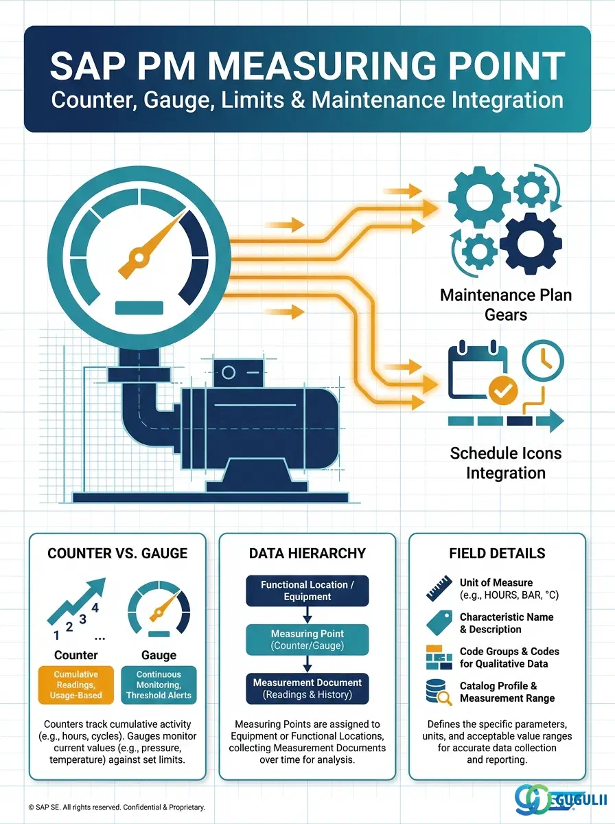
The Measuring Point is the master data object that defines a specific location on an equipment where a physical quantity is observed and recorded. It stores the measurement category (counter or gauge), unit of measure, threshold values, and the link back to the parent equipment. Every condition-based maintenance trigger and counter-based preventive maintenance plan in SAP PM relies on at least one Measuring Point and the Measurement Documents posted against it.
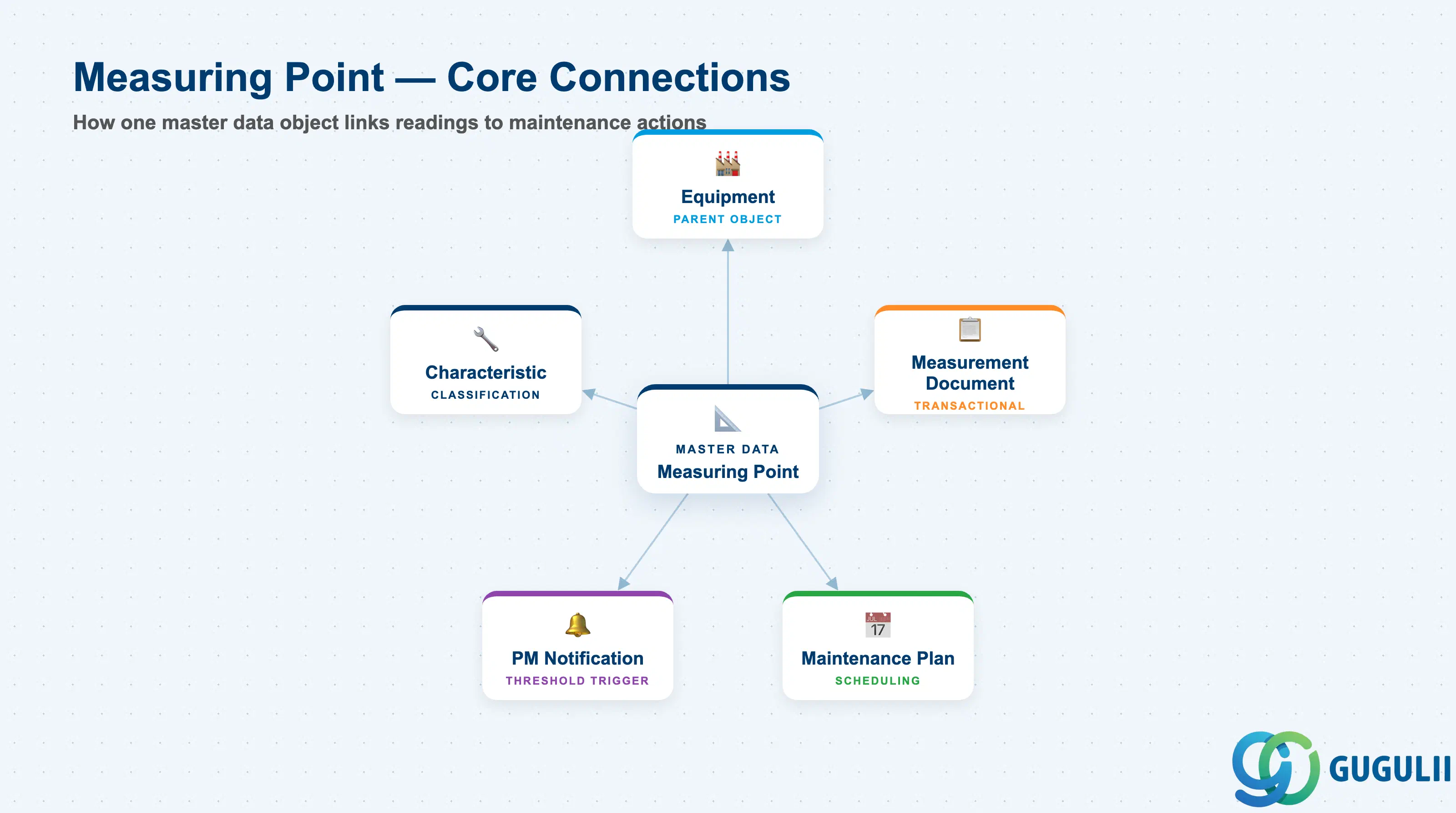
A Measuring Point represents a single, identifiable observation location on a technical object — for example, the vibration sensor mount on a motor bearing housing, or the operating-hours counter on a compressor. It is not a physical sensor itself; it is the SAP master data record that tells the system what kind of value to expect, in what unit, and how that value relates to maintenance actions.
| Aspect | Details |
|---|---|
| Role | Defines a specific measurement location on an equipment; stores measurement type, unit, and thresholds that drive condition-based and counter-based maintenance triggers |
| Modules using it | PM (primary owner — condition-based and counter-based maintenance), QM (quality inspection measurement points share the same object type in some configurations) |
| Transactions | IK01 (Create) / IK02 (Change) / IK03 (Display) / IK11 (Enter Measurement Document) / IK21 (Enter Multiple Measurement Documents) / IK41 (Display Measurement Documents for Point) |
| Key Tables | IMPTT (Measuring Point header) / IMRG (Measurement Document) / IMPTP (Measuring Point — Plant assignment) |
| S/4HANA note | Measuring Point and Measurement Document data model is unchanged from ECC. The Fiori app “Enter Measurement Readings” (F2254) replaces the classic IK11/IK21 transactions in a mobile-first adoption pattern. Counter-based maintenance plans (IP41/IP42) reference Measuring Points with category Counter. |
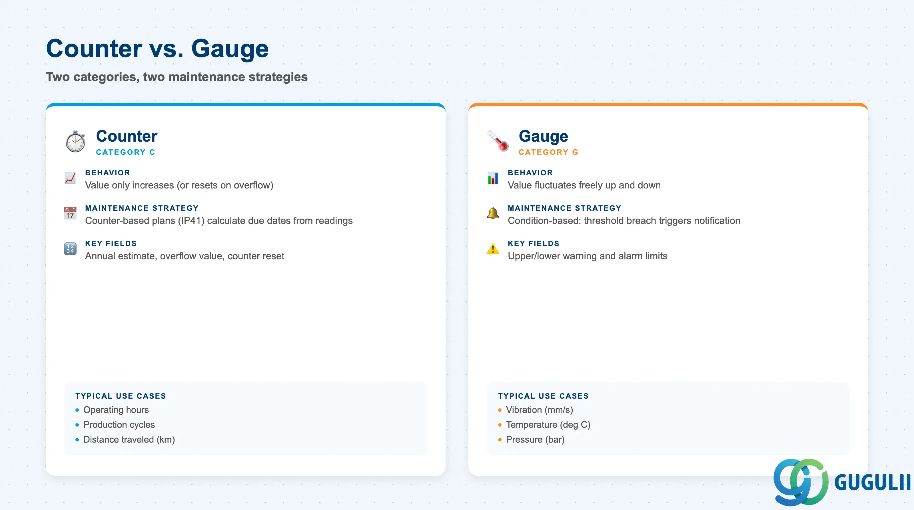
The Measuring Point category is the single most important configuration decision for this object. It determines whether the measurement accumulates over time (Counter) or simply records an instantaneous reading (Gauge), which in turn governs which maintenance planning strategies are available.
| Category | Code | Use Case | Key Behavior |
|---|---|---|---|
| Counter | C | Accumulated operating time (hours), production count (cycles), distance traveled (km) | Value can only increase (or reset to zero on overflow). Counter-based maintenance plans (IP41) use the counter reading to calculate due dates. Delta values are automatically derived between consecutive readings. |
| Gauge | G | Instantaneous physical quantity: vibration amplitude (mm/s), temperature (°C), pressure (bar), oil viscosity | Value can increase or decrease freely. Used in condition-based maintenance: a Measurement Document exceeding a threshold triggers automatic PM notification creation via the measuring point’s characteristic assignment. |
Design principle: Use Counter for time-based or cycle-based triggers where accumulated value drives the maintenance schedule; use Gauge for condition monitoring where an absolute threshold — not elapsed time — is the trigger. Mixing these up at setup time is costly to correct because counter-based maintenance plans must be restarted if the measuring point category changes.
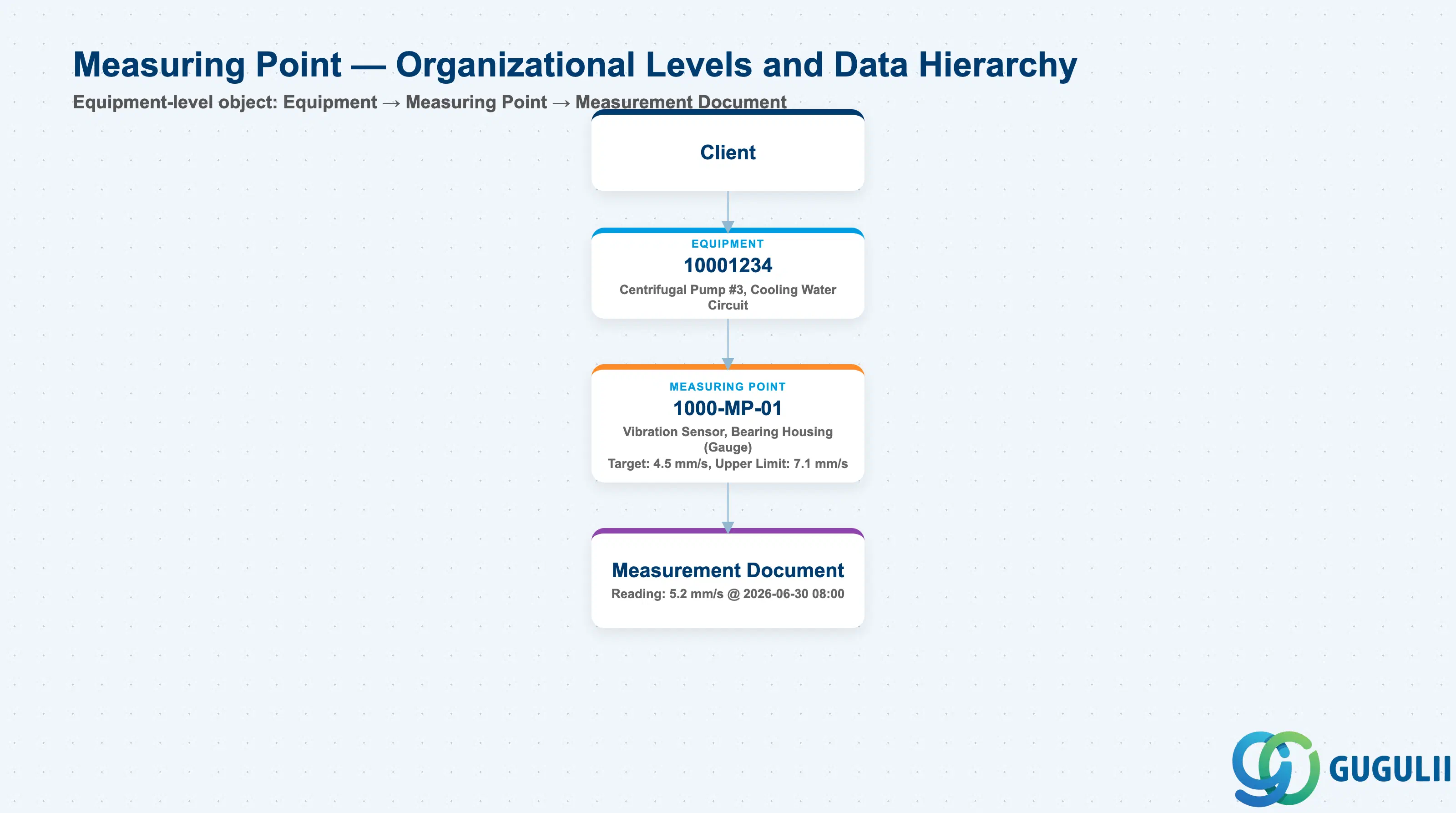
Data hierarchy with a concrete example
Client
   │
   └── Equipment 10001234
          Centrifugal Pump #3, Cooling Water Circuit
          │
          └── Measuring Point 1000-MP-01
                 Vibration Sensor, Bearing Housing (Gauge)
                 Target: 4.5 mm/s, Upper Limit: 7.1 mm/s
                 │
                 └── Measurement Document
                        Reading: 5.2 mm/s @ 2026-06-30 08:00
Key design decision: Decide at project start whether Measuring Points will be assigned to Equipment or to Functional Location. Equipment assignment is the most common pattern and supports counter-based maintenance plans directly. Functional Location assignment is used when the measurement point is location-specific rather than asset-specific (e.g., a fixed ambient temperature sensor in a room).
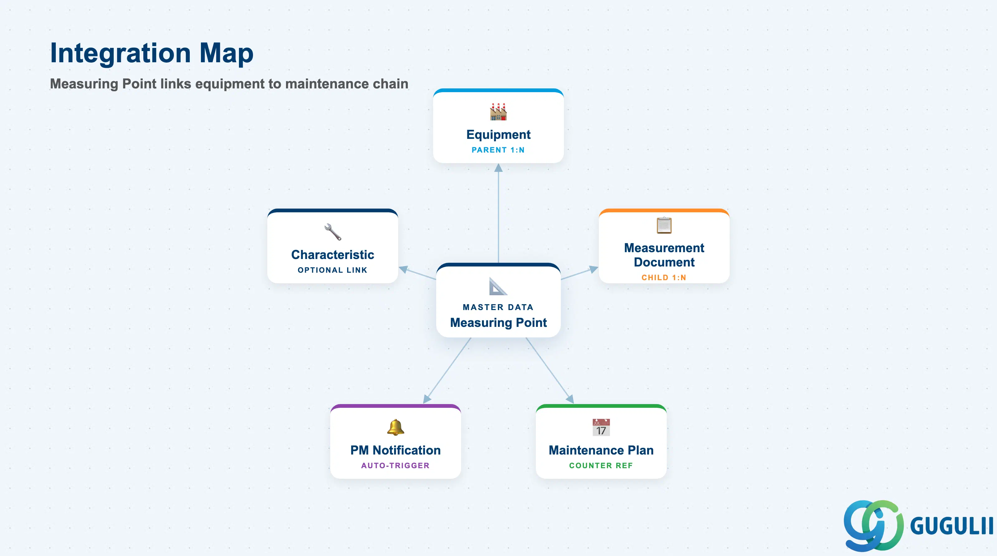
The Measuring Point does not stand alone. Its value lies in the connections it establishes between the physical measurement reading and the maintenance response chain.
| Object | Relationship | Practical Notes |
|---|---|---|
| Equipment | Parent object (1:N) | Every Measuring Point is assigned to exactly one Equipment (or Functional Location). The equipment must exist before the Measuring Point can be created. |
| Characteristic (PM Phase 2) | Optional — links measurement to classification | When a Gauge-type Measuring Point references a Characteristic with defined upper/lower limits, SAP can automatically create a PM Notification when a Measurement Document exceeds those limits. This is the core mechanism for condition-based maintenance. |
| Maintenance Plan (IP41 — Counter-Based) | Counter Measuring Point is the scheduling reference | A counter-based Maintenance Plan reads the current counter value from the Measuring Point to calculate the next planned maintenance date. The plan will not function without a valid Counter Measuring Point on the equipment. |
| Measurement Document (IK11) | Transactional child | Each measurement reading posted against the Measuring Point creates a Measurement Document (IMRG). The Maintenance Plan’s counter-based scheduling logic reads the most recent Measurement Document to determine elapsed usage. |
| PM Notification | Triggered by threshold breach | If condition monitoring is active, a Measurement Document reading that breaches the Characteristic limit automatically generates a PM Notification for corrective action. |
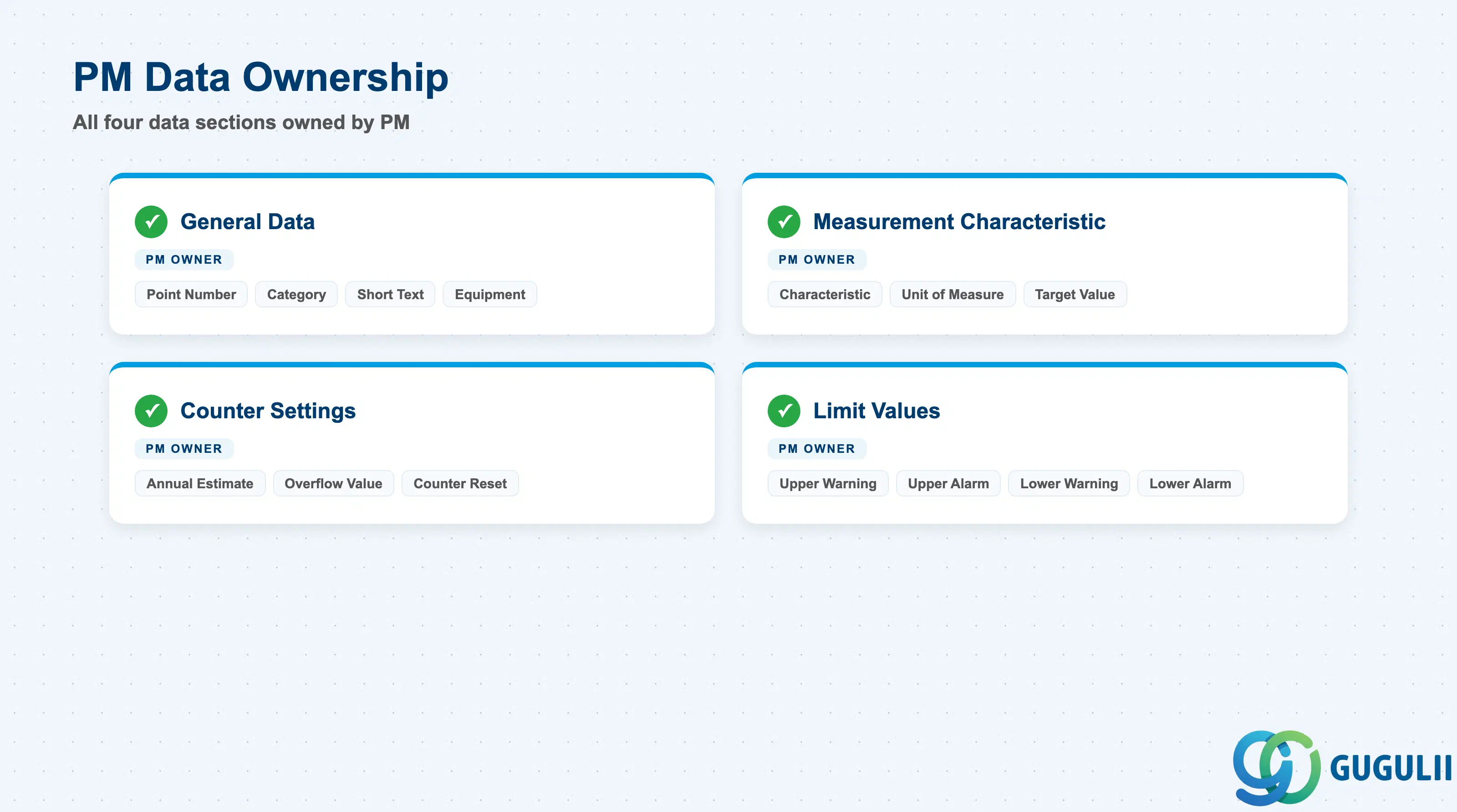
| Data Section | PM Involvement | Notes |
|---|---|---|
| General Data | ◎ Owner | Point number, category, short text, equipment assignment — fully owned by PM Administrator |
| Measurement Characteristic | ◎ Owner | Characteristic assignment, unit of measure, target value — PM owns but must coordinate with Classification team on characteristic definitions (Phase 2) |
| Counter Settings | ◎ Owner | Overflow value, annual estimate, counter reset indicator — applies only to Counter-type points; drives counter-based maintenance plan scheduling |
| Limit Values | ◎ Owner | Upper/lower warning and alarm limits — applies primarily to Gauge-type points; determines automatic notification generation thresholds |
Legend: ◎ = Owner / Critical
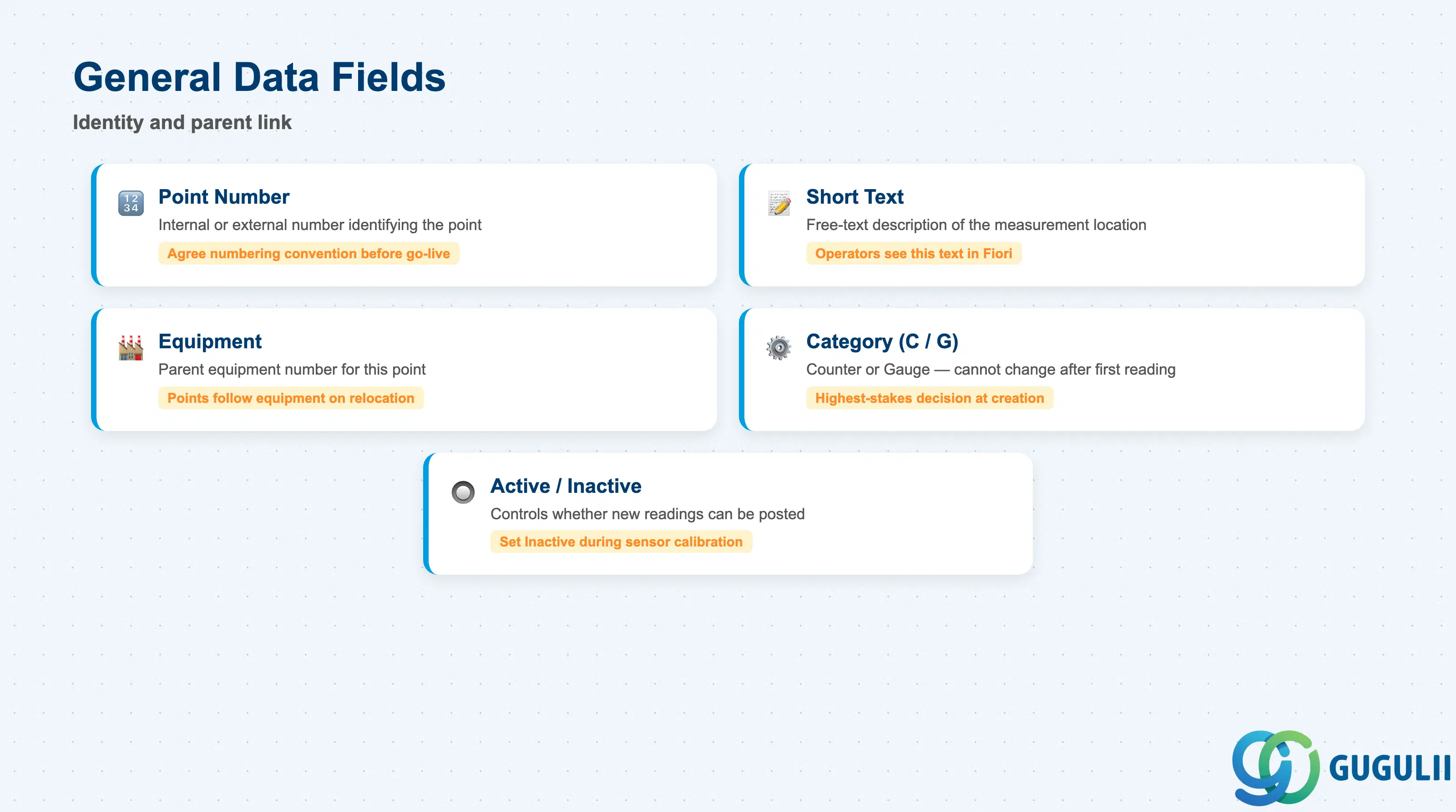
The General Data section identifies the Measuring Point and links it to its parent technical object. These fields are set at creation and rarely change during a plant’s operational life.
| Field | Description | Practical Usage |
|---|---|---|
| Measuring Point Number | Internal or external number identifying the point (e.g., “100001”) | Number range is configured in Customizing (PM → Basic Settings → Measuring Points). External numbering is common when point numbers must align with physical tag numbers on the shop floor. Agree on the numbering convention before go-live; renaming after Measurement Documents exist is not supported. |
| Short Text | Free-text description of the measuring location (e.g., “Compressor — Operating Hours Counter”) | Use a consistent naming convention that includes the measured quantity and unit in the description. Operators posting readings via Fiori see this text as their only identification of the point. |
| Equipment | Equipment number to which this Measuring Point is assigned | The equipment must have a valid installation in a Plant. If the equipment is dismantled and re-installed at a different Functional Location, the Measuring Points follow the equipment automatically. |
| Measuring Point Category | C (Counter) or G (Gauge) — see Section 1.2 | Set at creation and cannot be changed after the first Measurement Document is posted. This is the single highest-stakes decision in Measuring Point configuration. |
| Active/Inactive Indicator | Controls whether new Measurement Documents can be posted to this point | Set to Inactive when a measuring point is temporarily out of service (e.g., sensor being calibrated). Active is the default. Counter-based maintenance plans check this flag before calculating the next due date. |
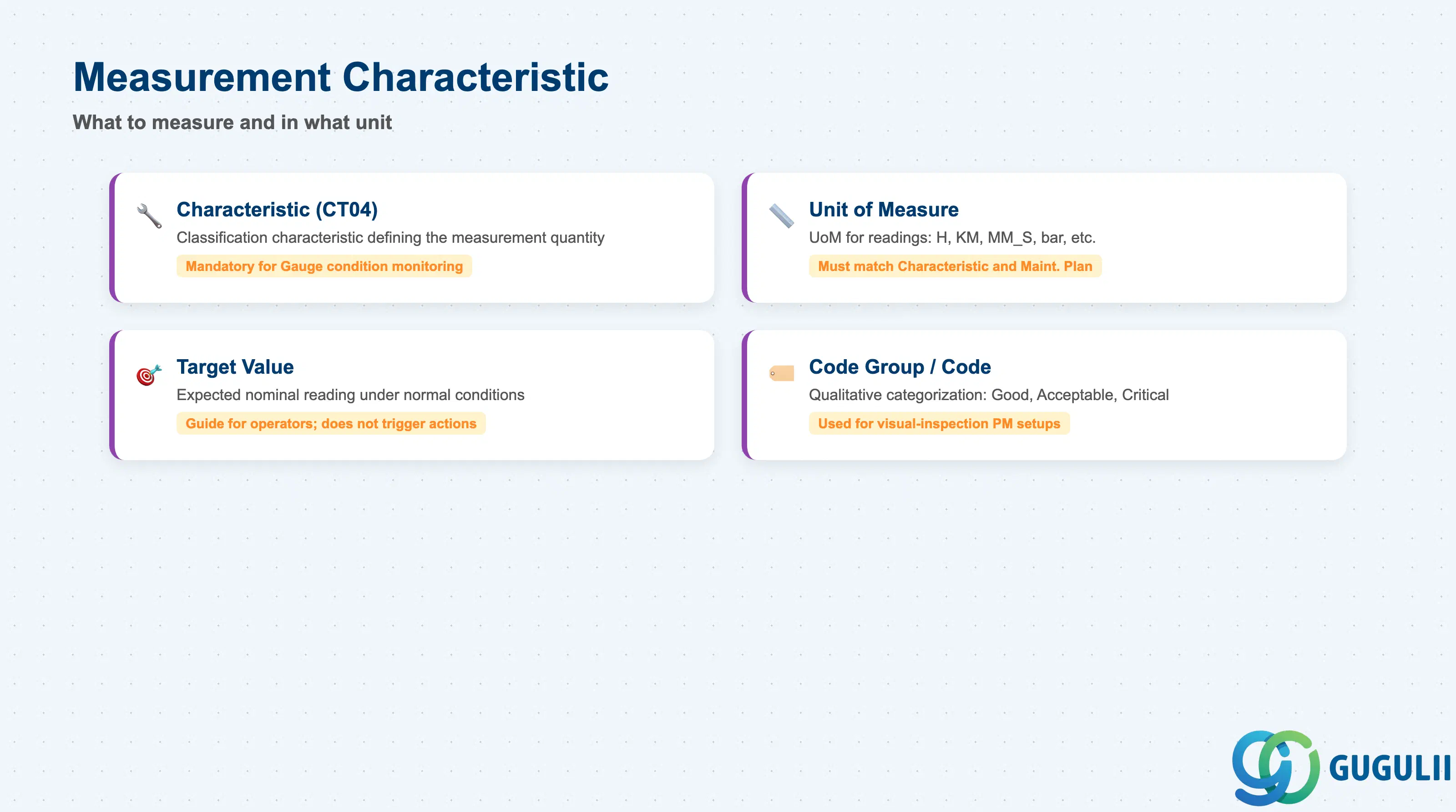
The Measurement Characteristic section defines what physical quantity is being measured and in what unit. It also provides the optional link to the Classification system that enables automated condition monitoring.
| Field | Description | Practical Usage |
|---|---|---|
| Characteristic | Reference to a Classification characteristic (CT04) that defines the measurement quantity and its data type | Mandatory for Gauge-type points where automatic notification generation on threshold breach is required. For simple Counter-type points (operating hours only), a characteristic is optional but recommended to ensure consistent unit management. The characteristic must already exist (Phase 2 prerequisite). |
| Unit of Measure | UoM for the measurement reading (e.g., H for hours, KM for kilometres, MM_S for mm/s vibration) | Must match the unit defined on the referenced Characteristic. A mismatch causes posting errors in IK11. For counter points driving maintenance plans, the unit must also be consistent with the cycle unit defined in the Maintenance Plan (IP41). |
| Target Value | Expected nominal reading at the measuring point under normal operating conditions | Used as the reference point for gauge-type condition monitoring. The target value appears in Measurement Document entry screens as a guide for operators. It does not trigger actions by itself — only the Limit Values in Section 2.4 trigger notifications. |
| Code Group / Code | Optional categorization of measurement readings into qualitative codes (e.g., “Good,” “Acceptable,” “Critical”) | Used when measurements are qualitative rather than numerical (e.g., visual inspection results). A code group is defined in Customizing (PM → Measuring Points → Code Groups). Rarely used in counter-based or vibration-monitoring scenarios but common in quality-inspection-adjacent PM setups. |
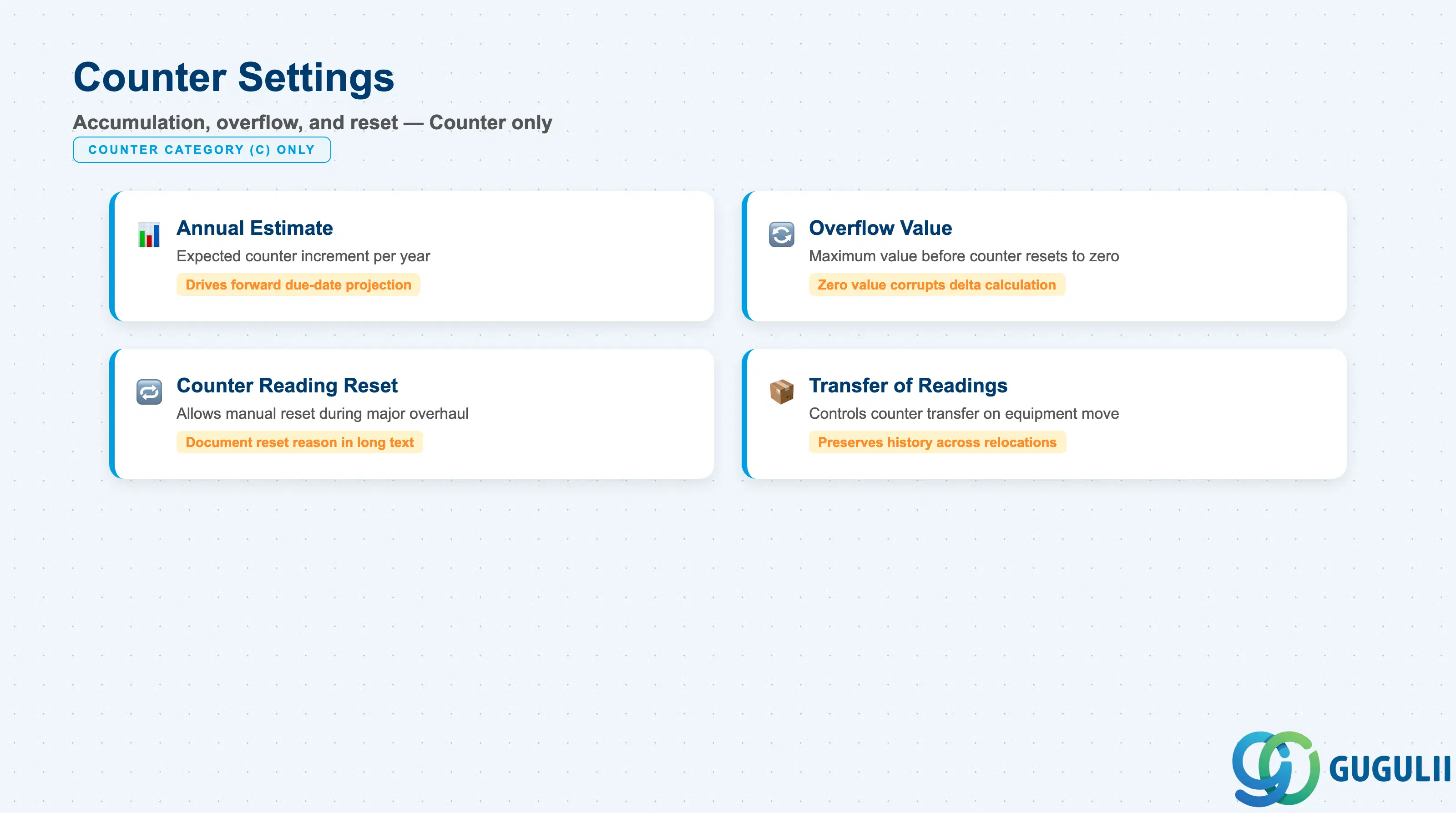
Counter Settings apply exclusively to Measuring Points with category C (Counter). These fields govern how the system handles the accumulation of counter values and how the counter-based Maintenance Plan calculates scheduling.
| Field | Description | Practical Usage |
|---|---|---|
| Annual Estimate | Expected counter increment per year (e.g., 8,000 hours/year for a continuously running compressor) | This value is used by the counter-based Maintenance Plan (IP41) to project forward due dates when no recent Measurement Document has been posted. If the annual estimate is unrealistic, the Maintenance Plan will generate call orders on incorrect dates. Review and update annually if operating patterns change significantly. |
| Overflow Value | The maximum counter value before the counter resets to zero (e.g., 99,999 hours) | SAP uses this to correctly compute the delta when a counter overflow occurs. If this field is left at zero, an overflow event will be misinterpreted as a large negative delta, corrupting the maintenance plan scheduling. Set this value to match the physical counter’s maximum display value. |
| Counter Reading Reset | Indicator that allows the counter to be manually reset to zero via a Measurement Document with the overflow flag set | Used when a physical counter is replaced or reset during a major overhaul. After a reset, the system recalculates the annual estimate baseline from the new zero. Document the reason for the reset in the Measurement Document long text for audit trail purposes. |
| Transfer of Counter Readings | Controls whether counter readings are transferred when equipment is moved or dismantled | When equipment is moved between functional locations, existing counter readings follow the equipment. This setting ensures the maintenance plan history is preserved across equipment relocations. |
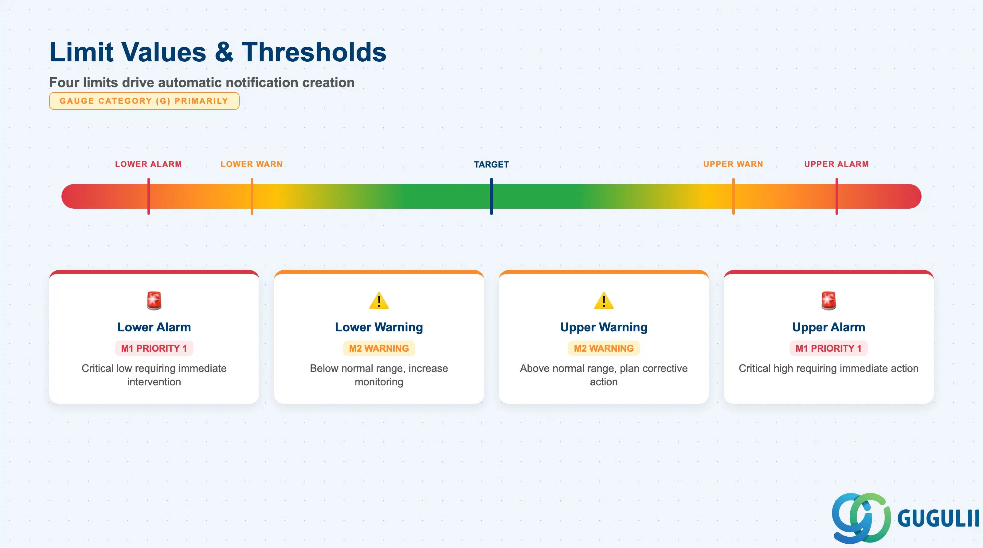
Limit Values apply primarily to Gauge-type Measuring Points and define the thresholds at which the system automatically creates a PM Notification. This is the core mechanism of condition-based maintenance in SAP PM.
| Field | Description | Practical Usage |
|---|---|---|
| Upper Warning Limit | Measurement value above which a warning-level PM Notification (type M2) is automatically created | Set to the value at which the maintenance team should begin monitoring the asset more closely, but corrective action is not yet urgent. For a vibration sensor on a motor, this might be 4.5 mm/s (ISO 10816 Zone B/C boundary). |
| Upper Alarm Limit | Measurement value above which an alarm-level PM Notification (type M1) is automatically created | Set to the value requiring immediate corrective action (ISO 10816 Zone D boundary, e.g., 7.1 mm/s). The Notification priority should reflect the urgency; many implementations set alarm-level notifications to Priority 1 (immediate). |
| Lower Warning Limit | Measurement value below which a warning-level notification is triggered | Used for quantities where a drop below a threshold indicates a problem — for example, oil pressure below 1.5 bar on a lubrication system. |
| Lower Alarm Limit | Measurement value below which an alarm-level notification is triggered | Typically set at the critical low threshold requiring immediate shutdown or intervention. Must be lower than the lower warning limit; SAP validates this on save. |
Prerequisite: Automatic Notification creation on threshold breach requires that the Measuring Point references a Characteristic (Section 2.2) with the limits defined there, OR that limits are set directly on the Measuring Point. Both methods are supported; the direct Measuring Point limits are evaluated first. Confirm during design which approach is used to avoid duplicate notifications.
| ID | Category | Title |
|---|---|---|
| pm-001 | Overview | What is SAP PM? |
| ID | Category | Title |
|---|---|---|
| pm-a01 | Overview | SAP PM Master Data: Overview, Hierarchy & Relationships |
| pm-a02-01 | Master Data | SAP PM Functional Location |
| pm-a02-02 | Master Data | SAP PM Equipment |
| pm-a03-01 | Master Data | SAP PM Class |
| pm-a03-02 | Master Data | SAP PM Characteristic |
| pm-a04-01 | Master Data | SAP PM Measuring Point 📍 |
| pm-a05-01 | Master Data | SAP PM Work Center |
| pm-a06-01 | Master Data | SAP PM Material Master |
| pm-a05-02 | Master Data | SAP PM Task List |
| pm-a05-03 | Master Data | SAP PM Production Resource Tool |
| pm-a06-03 | Master Data | SAP PM Maintenance BOM |
| pm-a07-01 | Master Data | SAP PM Maintenance Item |
| pm-a07-02 | Master Data | SAP PM Maintenance Plan |
| ID | Category | Title |
|---|---|---|
| pm-b01 | Overview | SAP PM Transactions: Process Flow, Hierarchy & Relationships |