Title here
Summary here

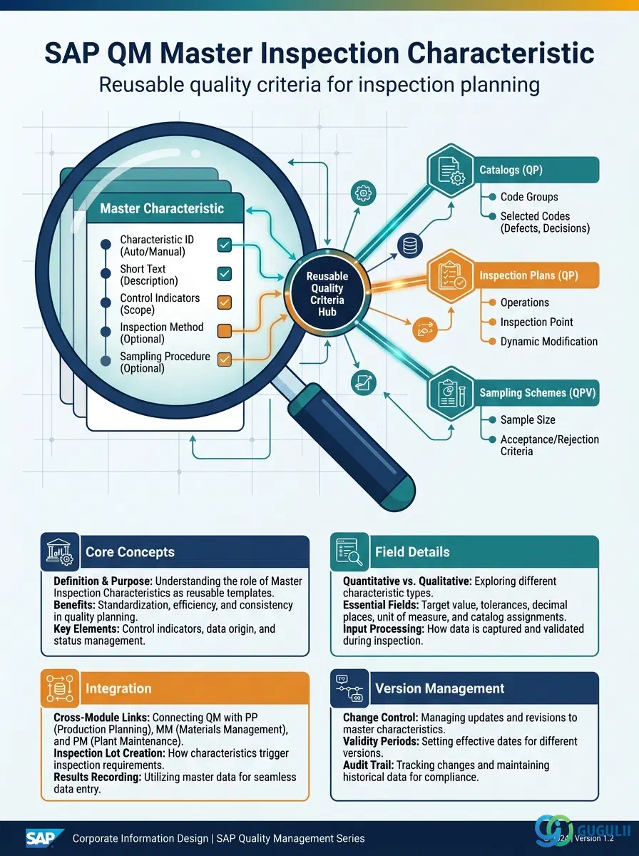
The Master Inspection Characteristic (MIC) is the reusable quality criterion that defines exactly what is measured or evaluated in a quality inspection. It stores the characteristic type (quantitative or qualitative), measurement unit, tolerance limits, and catalog assignments that drive results recording at the shop floor. Every Inspection Plan references one or more MICs to specify its inspection scope, and shared MICs eliminate duplicate maintenance when the same criterion applies to multiple materials or processes.
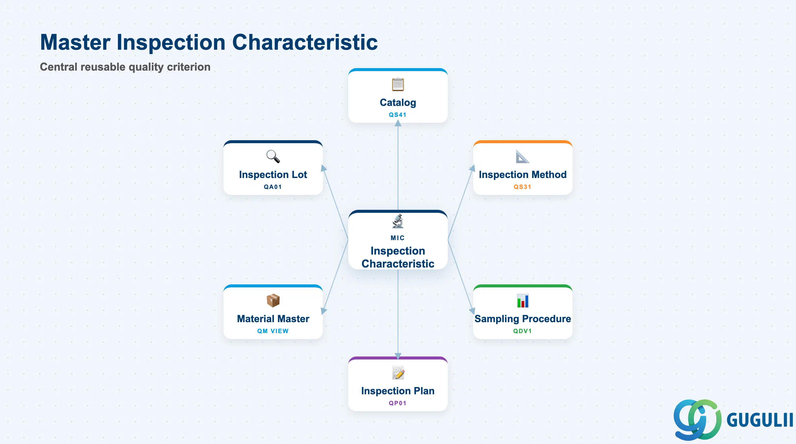
The Master Inspection Characteristic is a reusable inspection criterion that decouples the definition of “what to inspect” from the plan that specifies “how and when to inspect.” A single MIC can be assigned to many Inspection Plans across different materials, work centers, and inspection types, ensuring that the measurement standard remains consistent and centrally managed.
| Aspect | Details |
|---|---|
| Role | Defines the inspection criterion: type of measurement, units, tolerances, and result evaluation logic |
| Modules using it | QM (primary owner — all inspection types), PP (in-process inspection via Inspection Plan operations), MM (goods-receipt inspection tied to Material Master QM View) |
| Transactions | QS21 (Create) / QS22 (Change) / QS23 (Display) / QS2X (Mass display) |
| Key Tables | QPMK (MIC master header and characteristic attributes) / QPMD (MIC defect catalog assignment) |
| S/4HANA note | MIC structure unchanged from ECC. Fiori app “Manage Master Inspection Characteristics” (F2358) provides a modern UI with version overview, but QS21/QS22/QS23 remain the primary maintenance transactions in most implementations. |
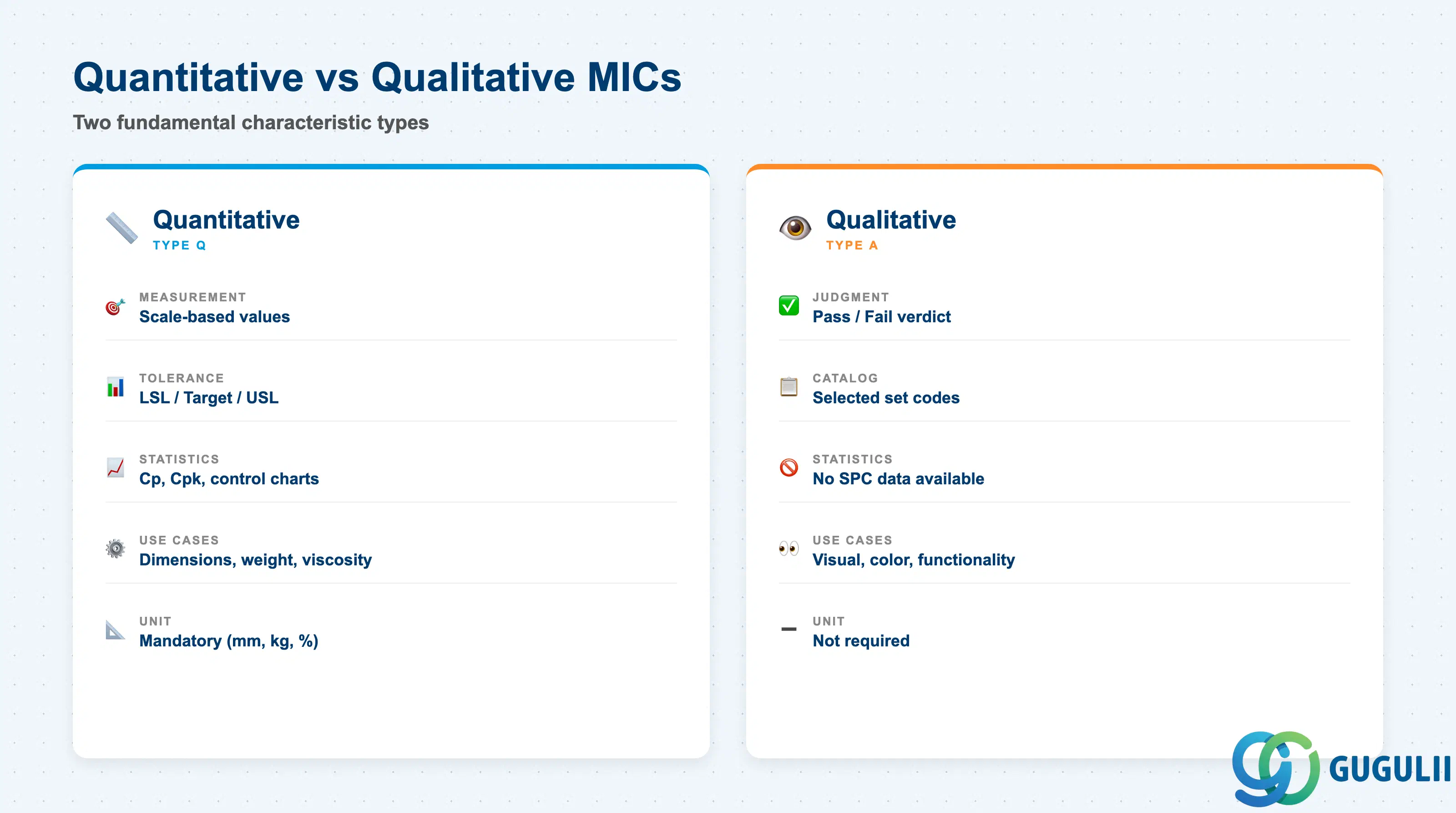
The most fundamental design decision for any MIC is whether it is quantitative (measured on a scale) or qualitative (pass/fail or attribute-based). This choice controls the entire results recording experience and the statistical evaluation available for that characteristic.
| Characteristic Type | Code | Use Case | Key Behavior |
|---|---|---|---|
| Quantitative | Q | Dimensional checks, weight, viscosity, tensile strength — any measured value | Upper and lower specification limits are defined. The system computes process capability (Cpk) and triggers defect recording when results fall outside tolerance. Measurement unit is mandatory. |
| Qualitative | A | Visual inspection, color check, functionality verification — pass/fail judgment | No measurement unit. Result is recorded as “Accepted” or “Rejected” based on a selected set from the defect catalog. Simpler to set up but no SPC data. |
| Summarized Characteristic | S | Summary of multiple sub-characteristics rolled into one valuation | Used when individual sub-inspection results must be aggregated into a single accepted/rejected verdict. Less common; typically reserved for complex final inspections. |
| Reference to Another Characteristic | R | Reuse tolerance limits and settings from a master reference MIC | Inherits all settings from the referenced MIC at plan assignment time. Useful for standardizing tolerance bands across a product family without maintaining multiple independent records. |
Design principle: Decide the characteristic type at blueprint. Changing a quantitative MIC to qualitative after results have been recorded requires archiving all historical inspection lots using that MIC — a costly remediation in production systems.
The Inspection Characteristic (IC) master is entirely client-level — one IC such as “IC-DIA” (Diameter) is defined once and can be reused across any plant, material, or inspection plan. It does not belong to a plant or material by itself; it becomes plant/material-specific only once it is copied into an Inspection Plan Operation.
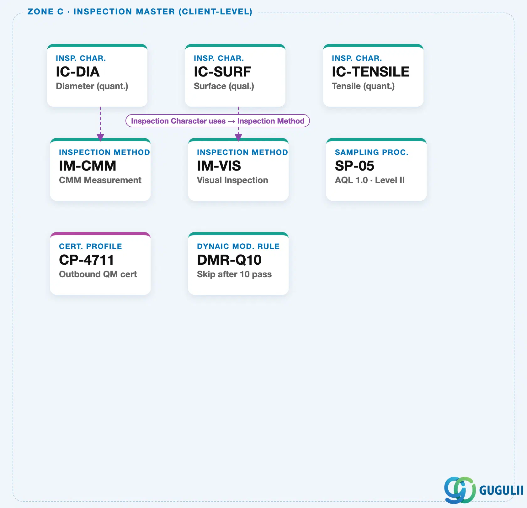
Two of IC’s neighboring client-level masters are directly linked from the IC itself: an IC references exactly one Inspection Method (how the value is measured), and optionally a Certificate Profile (for outbound quality certificates). Sampling Procedure and Dynamic Modification Rule are also client-level masters used during inspection, but they are assigned at the inspection plan/operation level, not on the IC record itself — they sit alongside IC as siblings, not as its children.
The IC’s second half of the picture is plant-level: once copied into an operation, it becomes an Insp. Characteristic that carries its own concrete value and an optional back-reference to the originating IC.
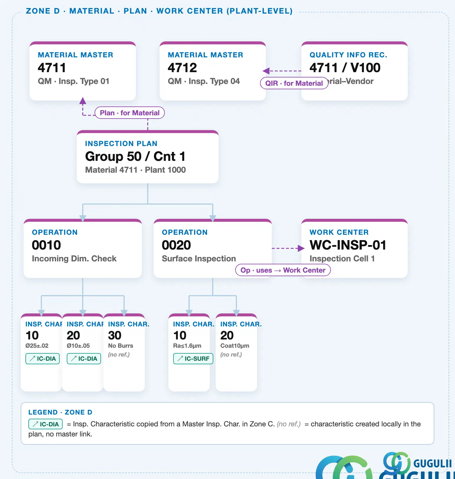
Data hierarchy with a concrete example
Client 100
   │
   ├── IC "IC-DIA"        Diameter (quant.)
   │      │
   │      └── uses ──> Inspection Method "IM-CMM"   CMM Measurement
   │
   ├── IC "IC-SURF"       Surface (qual.)
   │      │
   │      └── uses ──> Inspection Method "IM-VIS"   Visual Inspection
   │
   ├── Sampling Procedure "SP-05"          AQL 1.0 · Level II
   ├── Dynamic Mod. Rule "DMR-Q10"         Skip after 10 pass
   └── Certificate Profile "CP-4711"       Outbound QM cert

Plant 1000
   │
   └── Inspection Plan "Group 50 / Cnt 1"   Material 4711
          │
          ├── Operation 0010   Incoming Dim. Check
          │      ├── Insp. Char. 10   Ø25±.02mm   ── copied from ──> IC "IC-DIA"
          │      ├── Insp. Char. 20   Ø10±.05mm   ── copied from ──> IC "IC-DIA"
          │      └── Insp. Char. 30   No Burrs    (no master ref.)
          │
          └── Operation 0020   Surface Inspection
                 └── Insp. Char. 10   Ra≤1.6µm    ── copied from ──> IC "IC-SURF"
Design principle: Keep Inspection Characteristics client-level and reusable. An IC only becomes plant/material-specific the moment it is copied into an operation as an Insp. Char. — the master itself stays generic so the same “IC-DIA” can serve every plant and material that measures a diameter the same way.
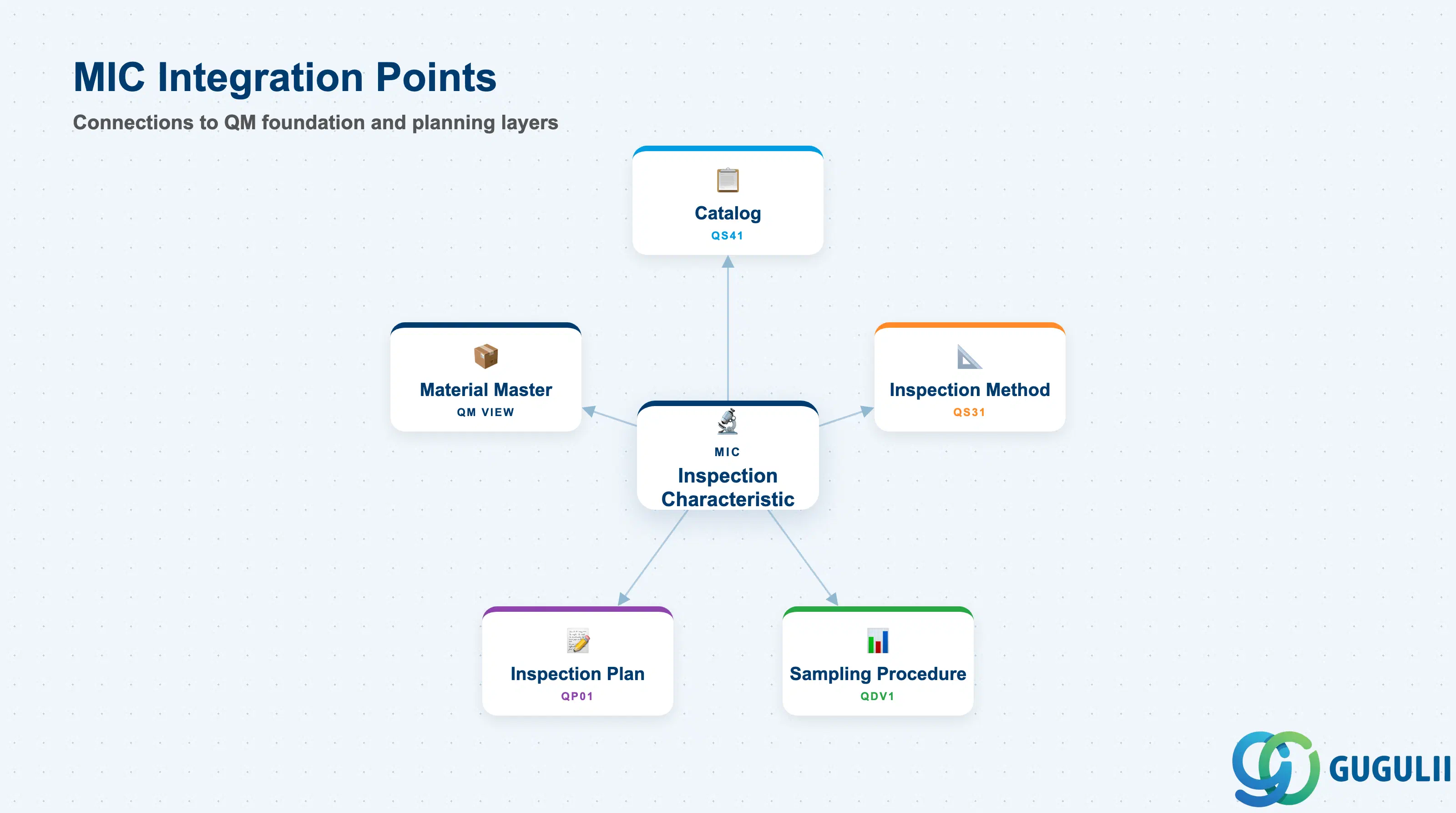
The Master Inspection Characteristic sits at the intersection of the QM foundation layer and the planning layer. It draws from Catalogs and Inspection Methods, and feeds into Inspection Plans, which in turn activate on Material Masters.
| Object | Relationship | Practical Notes |
|---|---|---|
| Catalog (QS41) | MIC references selected sets from defect, cause, and action catalogs | A qualitative MIC requires at least a Usage Decision catalog assignment (Catalog Type 1) to drive the accepted/rejected result. Without this, results recording is incomplete and the inspection lot cannot be closed. |
| Inspection Method (QS31) | MIC can reference an Inspection Method for measurement procedure documentation | The method is informational at the MIC level — it describes how to perform the measurement. Referencing a method on the MIC ensures consistent procedure documentation even when the same criterion is used in different Inspection Plans. |
| Sampling Procedure (QDV1) | MIC can carry a default sampling procedure | When a sampling procedure is assigned at the MIC level, it is proposed as the default at Inspection Plan characteristic assignment. Plan-level overrides are possible, giving flexibility without losing the standard default. |
| Inspection Plan (QP01) | Many Inspection Plans reference one MIC | This N:1 relationship is the core value of the MIC. A dimensional tolerance defined once in the MIC propagates to all plans that reference it. When a specification changes, update the MIC once rather than updating every plan individually. |
| Material Master (QM View) | Inspection Plan (which uses MICs) is linked to the Material Master | The MIC influences inspection lot creation indirectly: when a material with an active QM inspection type generates an inspection lot, the lot’s characteristics are derived from the MIC definitions in the assigned Inspection Plan. |
| Inspection Lot | MIC characteristics appear as result recording lines in the inspection lot | During results recording (QE01/QE02), each MIC assigned to the plan operation becomes a row where the inspector enters measured values or pass/fail verdicts. |
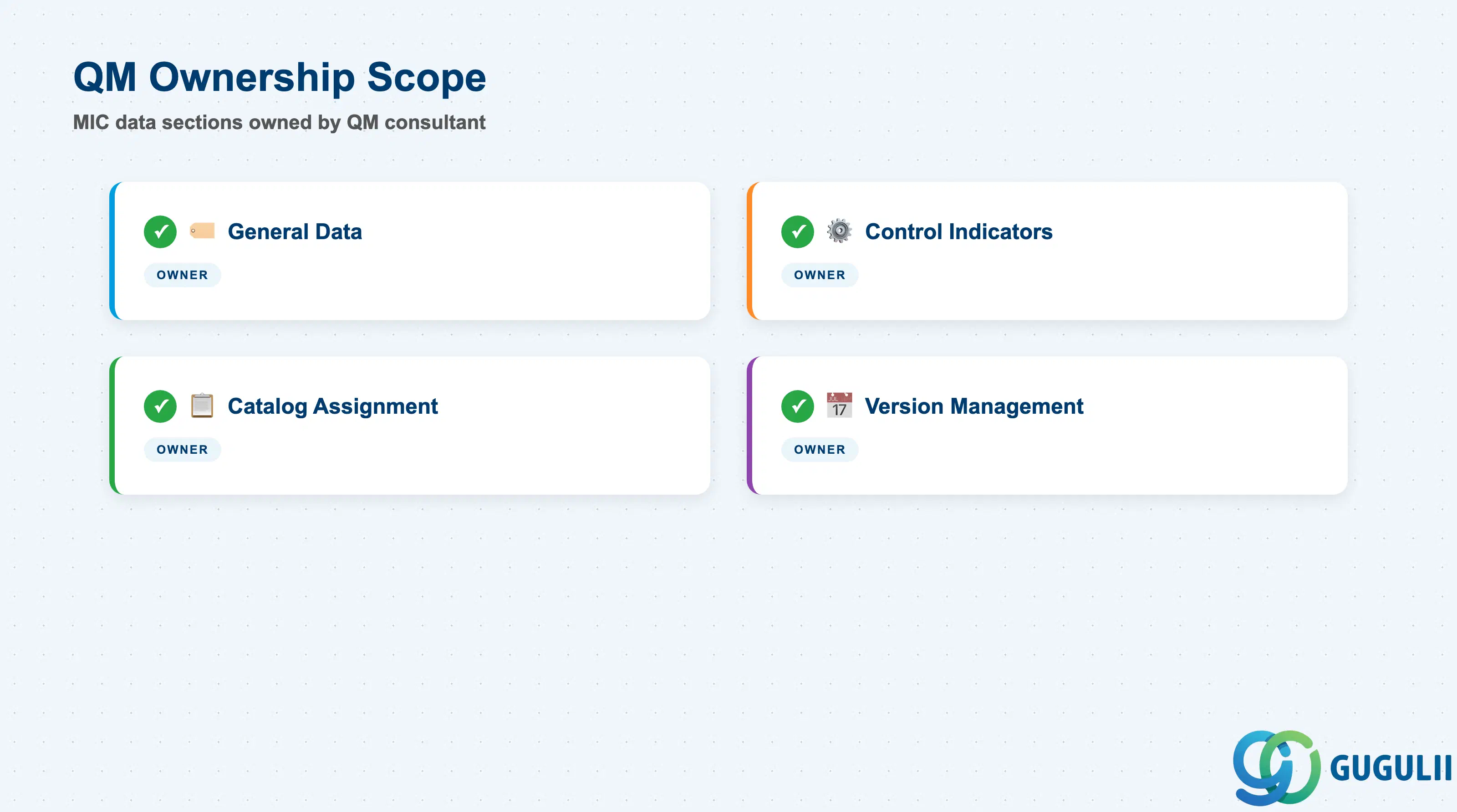
| Data Section | QM Involvement | Notes |
|---|---|---|
| General Data | ◎ Owner | Characteristic key, short text, plant, status — the identity and lifecycle of the MIC |
| Control Indicators | ◎ Owner | Quantitative/qualitative type, measurement unit, specification limits, target value — the core inspection logic |
| Catalog Assignment | ◎ Owner | Selected sets for defect, cause, action codes — drives results recording and defect classification |
| Version Management | ◎ Owner | Validity dates, version status, change document — controls when a revised specification takes effect |
Legend: ◎ = Owner / Critical, ○ = Direct involvement
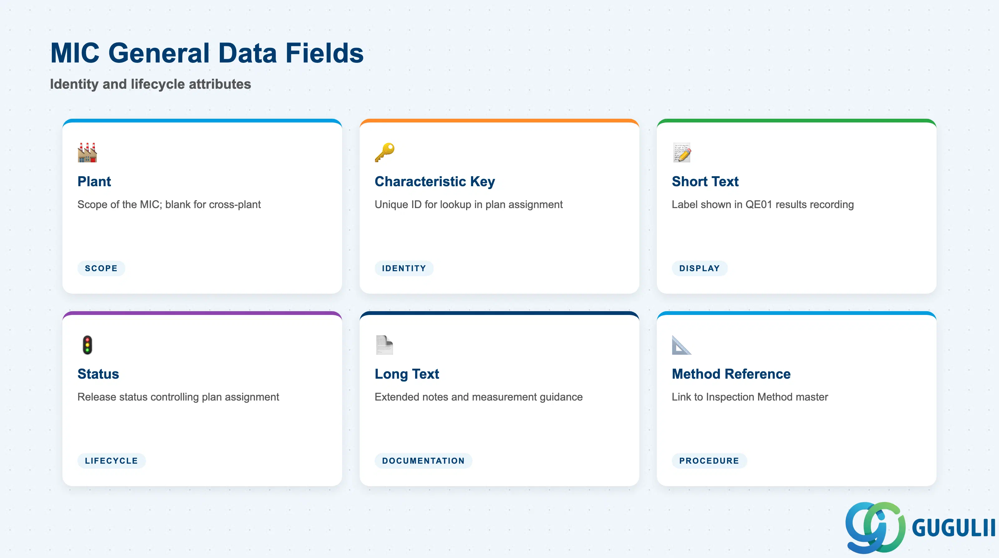
General Data forms the identity layer of the MIC. These fields determine how the characteristic is identified, where it is valid, and whether it is available for use in Inspection Plans.
| Field | Description | Practical Usage |
|---|---|---|
| Plant | Plant to which the MIC belongs | Defines the scope of the MIC. A blank plant creates a cross-plant characteristic; populating a plant restricts it to that plant. In multi-plant deployments, establish a naming convention that embeds the plant code or a “GLOBAL” prefix so plant-independent MICs are immediately distinguishable during plan maintenance. |
| Characteristic Key | Unique alphanumeric identifier for the MIC | The key is the primary lookup field in Inspection Plan characteristic assignment. Establish a structured naming convention early (e.g., DIM-001 for dimensional, VIS-001 for visual) — renaming MICs after they are referenced in active plans requires careful archiving and reassignment. |
| Short Text | Brief description of the inspection criterion | Appears as the characteristic label in QE01 results recording screens. Keep it concise but unambiguous: “Outer Diameter (mm)” is better than “OD” alone. Used in standard QM reports and inspection lot printouts. |
| Status | Release status of the MIC (e.g., 4 = Released) | Only MICs with Released status (4) can be assigned to Inspection Plans for production use. During blueprint and testing, use a preliminary status (1 or 2) to prevent accidental use. Set to Released only after sign-off by the QM process owner. |
| Long Text | Extended description, measurement procedure notes | Optional but recommended for complex characteristics. Appears in the Inspection Plan characteristic detail screen and can serve as a brief measurement instruction supplement to the formal Inspection Method. |
| Inspection Method Reference | Link to an Inspection Method master | Carries the measurement procedure documentation (instrument type, measurement conditions, reference standard). Assigning a method at the MIC level ensures procedure consistency across all plans that use the MIC. |
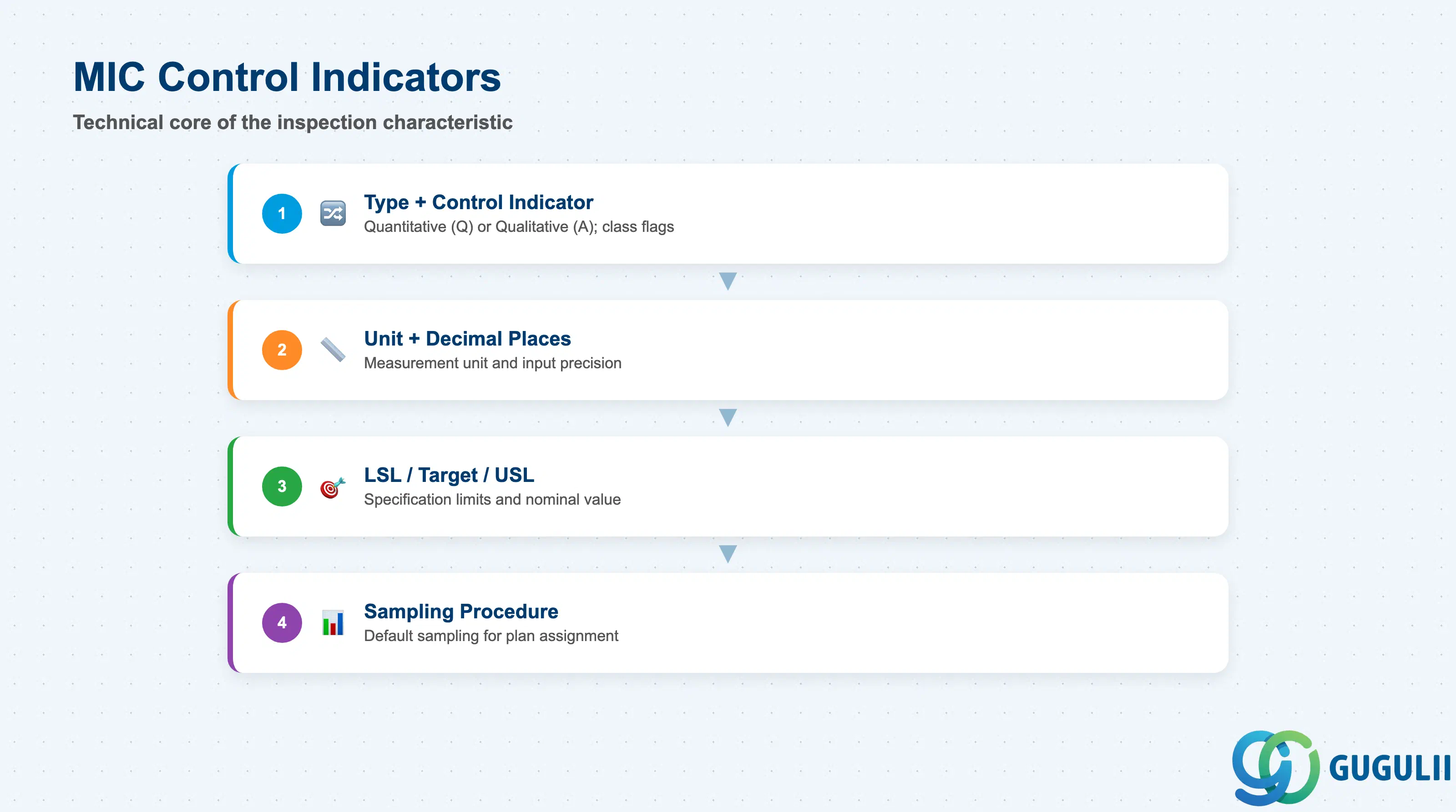
Control Indicators are the technical core of the MIC. They define exactly how the characteristic is measured, what constitutes a passing result, and how the system evaluates results to determine acceptance or rejection of an inspection lot.
| Field | Description | Practical Usage |
|---|---|---|
| Characteristic Type | Quantitative (Q) or Qualitative (A) | The most consequential setting on the MIC. Drives measurement unit requirement, results recording UI, and available statistical functions. Set at creation and treat as immutable in production — type changes require archiving historical data. |
| Control Indicator | Characteristic class flags (e.g., measurement, attribute, summarized) | A combination field that governs calculation type, SPC chart type, and whether the system can auto-accept based on measured values. Standard quantitative MICs use “M” (Measured Value); standard qualitative use “A” (Attribute). Confirm with the QM consultant lead before using non-standard values. |
| Measurement Unit | Unit for quantitative characteristics (e.g., mm, kg, %) | Must match the unit used by the measurement instrument and be defined in UoM Customizing. Inconsistent units between the MIC and the measuring gauge master are a common source of results recording errors during go-live testing. |
| Lower Specification Limit (LSL) | Minimum acceptable value for quantitative characteristics | Triggers a defect recording entry when a measured value falls below this threshold. Set to the engineering drawing tolerance lower bound. Document the source drawing revision in the MIC long text to maintain traceability when tolerances are updated. |
| Upper Specification Limit (USL) | Maximum acceptable value for quantitative characteristics | The upper tolerance bound. The system flags a characteristic as rejected when the measured value exceeds USL. Maintain LSL and USL together — a MIC with only one limit set is valid but unusual; confirm with the process engineer that a one-sided tolerance is intentional. |
| Target Value | Nominal or ideal value | Used in SPC calculations (Cp, Cpk) and as the center line in control charts. Set to the nominal dimension from the engineering specification. Leaving target value blank disables Cpk reporting for this characteristic, which may be acceptable for non-critical dimensions but should be a deliberate decision. |
| Decimal Places | Number of decimal places for result entry | Controls result input precision in QE01. Match to instrument resolution and specification precision (e.g., 2 decimal places for mm dimensions measured with a caliper, 3 for micrometer measurements). Setting fewer decimals than the instrument resolution loses data; more decimals implies false precision. |
| Sampling Procedure | Default sampling procedure for this MIC | Proposed when assigning the MIC to an Inspection Plan operation. Can be overridden at the plan level. Assigning a default here enforces a sampling standard for the characteristic across all plans that use it, reducing inconsistency between plans maintained by different QM administrators. |
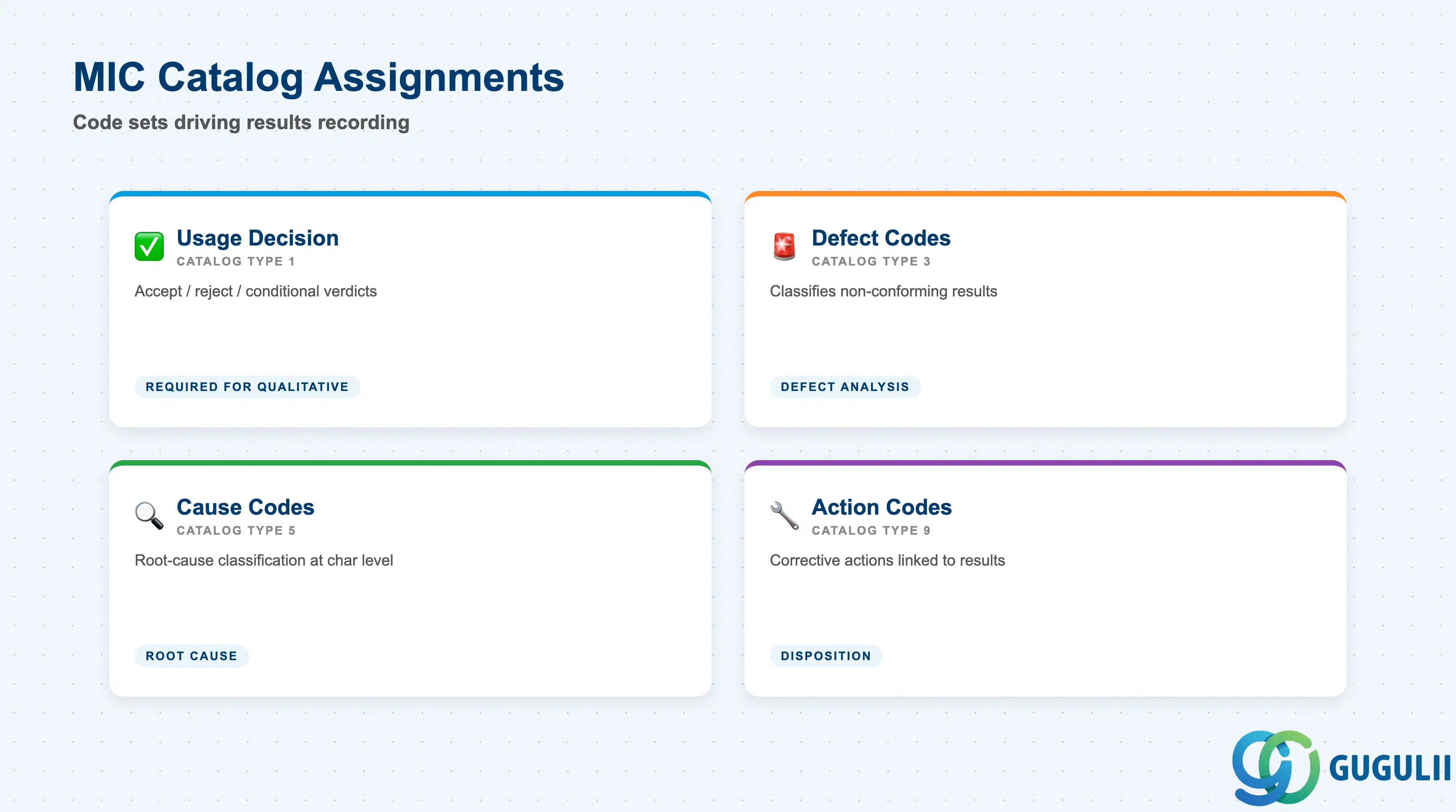
Catalog Assignment links the MIC to pre-defined code sets from the Catalog master (QS41). These assignments determine which defect codes, cause codes, and action codes inspectors can select during results recording, and which usage decisions are available when closing an inspection lot characteristic.
| Field | Description | Practical Usage |
|---|---|---|
| Selected Set (Catalog Type 1 — Usage Decision) | Code set for accepted/rejected/conditional verdicts | Required for qualitative MICs. The selected set restricts which usage decision codes are valid for this characteristic, preventing miscoding. For quantitative MICs, usage decisions are typically auto-generated from specification compliance but a selected set can still be assigned for manual override scenarios. |
| Selected Set (Catalog Type 3 — Defect Codes) | Code set listing possible defect types | Defines which defect classifications the inspector can record when a result is non-conforming (e.g., “Dimensional Out of Tolerance,” “Surface Scratch,” “Contamination”). Assign a catalog-type 3 selected set to every MIC where defect recording is expected — results without a defect code are difficult to analyze in QM reports and quality notifications. |
| Selected Set (Catalog Type 5 — Cause Codes) | Code set for root-cause classification | Enables root cause assignment at the characteristic level during results recording. Assign when this characteristic is part of a defect analysis workflow. Not all MICs require cause codes — prioritize critical-to-quality characteristics and those with historical defect patterns. |
| Selected Set (Catalog Type 9 — Action Codes) | Code set for corrective actions | Links corrective actions directly to the inspection characteristic result. Useful for characteristics where standard reactions are predefined (e.g., “Rework,” “Scrap,” “Return to Vendor”). Reduces dependency on quality notifications for routine disposition decisions. |
Prerequisite: Catalog selected sets must exist in QS41 before they can be assigned to MICs. Catalog setup (QM-A02-01) must be completed before MIC creation in every project. Attempting to assign a non-existent selected set causes a hard error at MIC save.
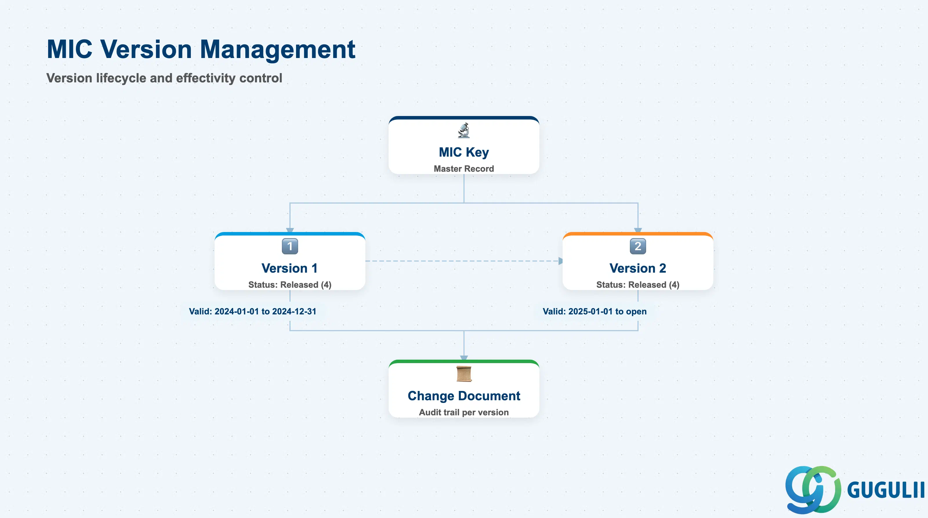
Version Management allows the MIC to evolve over time — for example, when engineering tolerances are tightened, a new version of the MIC becomes effective on a given date while historical inspection lots retain their original specification for traceability. This is one of the most operationally critical features of the MIC compared to characteristics defined inline in an Inspection Plan.
| Field | Description | Practical Usage |
|---|---|---|
| Version | Version number of this MIC definition | Each version is an independent record with its own validity period and status. Version numbers are system-assigned sequentially. Never delete a superseded version — historical inspection lots reference the version active at lot creation time, and deletion breaks traceability and audit trails. |
| Valid From | Start date of this MIC version’s effectivity | The date from which this version is used for new inspection lot characteristic assignment. Coordinate the Valid From date with the engineering change order (ECO) effective date and the Material Master revision level if applicable. A mismatch between the MIC Valid From and the ECO effective date is a common source of compliance findings during quality audits. |
| Valid To | End date of this MIC version’s effectivity | Automatically set when a new version supersedes this one, or manually entered for a planned end-of-life. Leave blank for an open-ended current version. |
| Status | Release status of this version | Mirrors the overall MIC status — each version must reach Released status (4) before it can be used in a production Inspection Plan. Use preliminary statuses (1 = Created, 2 = Reviewed) as workflow stages before the QM process owner grants final release. |
| Change Document | System-generated change log | Records every field change with user, timestamp, and old/new value. Provides the audit trail required for ISO 9001 document control and AS9100 aerospace quality system compliance. In regulated industries, supplement the system change document with a manual change reason entry in the long text. |
| ID | Category | Title |
|---|---|---|
| qm-001 | Overview | What is SAP QM? |
| ID | Category | Title |
|---|---|---|
| qm-a01 | Overview | SAP QM Master Data: Overview, Hierarchy & Relationships |
| qm-a02-01 | Master Data | SAP QM Catalog |
| qm-a02-02 | Master Data | SAP QM Master Inspection Characteristic 📍 |
| qm-a02-03 | Master Data | SAP QM Inspection Method |
| qm-a03-01 | Master Data | SAP QM Sampling Procedure |
| qm-a03-02 | Master Data | SAP QM Dynamic Modification Rule |
| qm-a05-01 | Master Data | SAP QM Material Master |
| qm-a04-01 | Master Data | SAP QM Work Center |
| qm-a04-02 | Master Data | SAP QM Inspection Plan |
| qm-a05-02 | Master Data | SAP QM Quality Info Record |
| ID | Category | Title |
|---|---|---|
| qm-b01 | Overview | SAP QM Transactions: Process Flow, Hierarchy & Relationships |